


Ensuring Product Reliability with Temperature Cycling Tests
Introduction
In the contemporary landscape of manufacturing, product reliability is not merely a desirable attribute but a fundamental requirement that underpins brand reputation, user safety, and economic viability. The operational lifespan of modern devices is critically challenged by the relentless stress of thermal expansion and contraction. These cyclical temperature variations, encountered during transportation, storage, and daily operation, induce mechanical fatigue, degrade material interfaces, and precipitate latent defects that can lead to catastrophic field failures. To proactively identify and mitigate these vulnerabilities, temperature cycling testing has emerged as an indispensable, scientifically rigorous methodology within the product validation lifecycle. This article delineates the principles, applications, and critical implementation of temperature cycling tests, with a specific examination of advanced instrumentation such as the LISUN HLST-500D Thermal Shock Test Chamber, which provides the controlled, extreme environmental transitions necessary to accelerate failure mechanisms and ensure robust product design.
Fundamental Principles of Thermal Stress and Failure Mechanisms
Temperature cycling tests are predicated on the basic physics of thermal expansion, where materials expand when heated and contract when cooled. The coefficient of thermal expansion (CTE) is a material-specific property; when dissimilar materials with mismatched CTEs are bonded or assembled—such as silicon dies to ceramic substrates, solder joints to printed circuit boards (PCBs), or polymer housings to metal frames—thermal cycling induces shear and tensile stresses at their interfaces. These repetitive stresses are the primary drivers of several key failure modes.
The most prevalent failure mechanism is solder joint fatigue. Solder, typically a tin-silver-copper alloy, is a viscoplastic material. Continuous cycling between temperature extremes causes creep and stress relaxation within the joint. Over hundreds or thousands of cycles, this leads to the initiation and propagation of microcracks, ultimately resulting in increased electrical resistance or an open circuit. For components like Ball Grid Arrays (BGAs) or Quad Flat No-lead (QFN) packages, this is a dominant reliability concern.
Delamination is another critical failure mode, affecting multi-layer structures. This includes the separation of copper traces from FR-4 PCB laminates, the detachment of underfill materials from semiconductor dies, or the peeling of conformal coatings. Thermal cycling exacerbates weaknesses in adhesive bonds, leading to interfacial cracks that can compromise electrical insulation, thermal conductivity, and mechanical integrity.
Furthermore, thermal cycling can accelerate other degradation processes. It can cause the outgassing of volatiles within materials, leading to voids. It can worsen the effects of tin whisker growth in certain plating finishes. For electromechanical components like relays, connectors, and switches, cycling can cause fretting corrosion at contact points or alter the mechanical actuation force. The primary objective of accelerated temperature cycling is to subject the unit under test (UUT) to a condensed lifetime of these stresses in a controlled laboratory environment, thereby forcing latent defects to manifest as observable failures.
Designing an Effective Temperature Cycling Test Profile
The efficacy of a temperature cycling test is wholly dependent on the carefully constructed test profile. This profile is not arbitrary; it is a defined sequence of temperature extremes, transition rates, and dwell times engineered to simulate or accelerate real-world conditions. Key parameters must be judiciously selected based on the product’s application, materials, and relevant industry standards.
The temperature extremes (high temperature, T_H, and low temperature, T_L) must bracket the product’s specified operational and storage limits, often with an added margin for safety and acceleration. For instance, an automotive engine control unit (ECU) may be tested from -40°C to +125°C to account for under-hood conditions and cold-start scenarios in arctic climates.
The dwell time at each extreme is critical. It must be sufficient for the entire UUT—not just its surface—to achieve thermal equilibrium. Inadequate dwell results in a thermal gradient across the assembly, which does not accurately represent the full stress condition. Dwell times are typically determined by the product’s thermal mass and can range from 30 minutes to several hours.
Perhaps the most significant acceleration factor is the transition rate between extremes. While real-world temperature changes may be gradual, rapid transitions in a test chamber dramatically increase the strain rate on materials, accelerating fatigue. Rates of 10°C/min to 30°C/min are common in standard cycling, while thermal shock testing employs extreme rates, often achieved by mechanically transferring the UUT between separate hot and cold zones.
The number of cycles is then derived from the target product lifetime. Using validated acceleration models, such as the Coffin-Manson relationship (which correlates cycles-to-failure with the temperature swing), a test duration simulating 10 or 15 years of use can be calculated. Common reference standards include IEC 60068-2-14 (environmental testing procedures), JESD22-A104 (temperature cycling), and MIL-STD-810H for military and aerospace applications.
The Role of Advanced Instrumentation: The LISUN HLST-500D Thermal Shock Test Chamber
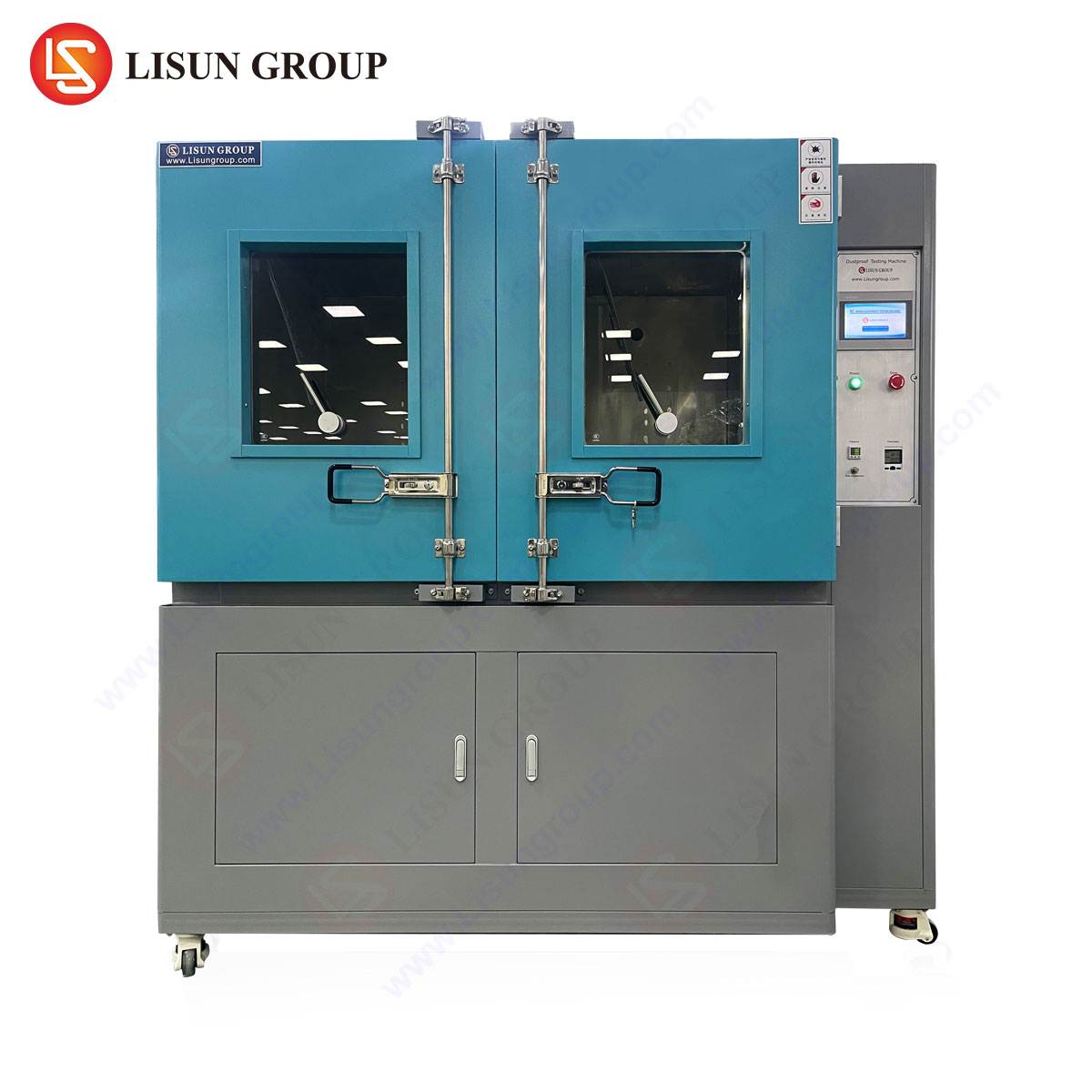
To execute high-stress temperature cycling, particularly thermal shock profiles with maximum acceleration, specialized equipment is mandatory. The LISUN HLST-500D Thermal Shock Test Chamber exemplifies this category of instrumentation, designed to deliver extreme thermal transitions with precision and repeatability.
The HLST-500D operates on a two-zone (or three-zone) principle. It features independent high-temperature and low-temperature chambers. The test basket, holding the UUT, is mechanically transferred between these zones in less than 10 seconds, initiating an immediate and severe thermal shock. This rapid transfer is the defining characteristic that differentiates thermal shock from conventional temperature cycling.
Specifications and Testing Principles:
- Test Volume: 500 liters, accommodating large or multiple test items.
- Temperature Range: High Temperature Chamber: +60°C to +200°C; Low Temperature Chamber: -10°C to -65°C (or lower with optional LN2 cooling).
- Recovery Time: After specimen transfer, the chambers rapidly recover to their setpoint temperatures, typically within 5 minutes, ensuring the specified extreme is maintained for the duration of the dwell.
- Basket Transfer Time: < 10 seconds, ensuring minimal temperature stabilization during transit and maximizing the thermal strain on the UUT.
- Control System: A programmable microprocessor controller allows for the creation of complex multi-segment test profiles, including pre-conditioning, cycling, and final stabilization. Data logging capabilities are integral for recording chamber performance and, if used, monitoring UUT response via in-situ electrical monitoring (a common companion setup).
Industry-Specific Applications and Use Cases
The HLST-500D’s capability to induce severe thermal stress makes it applicable across a spectrum of high-reliability industries.
- Automotive Electronics: Testing engine control modules, LiDAR sensors, battery management systems, and infotainment units for reliability against the shock of a cold start after a hot soak, or vice-versa.
- Aerospace and Aviation Components: Validating avionics, satellite components, and communication modules that must endure rapid temperature shifts during ascent/descent or when moving in/out of planetary shadow in space applications.
- Telecommunications Equipment: Stress-testing 5G base station amplifiers, optical transceivers, and core network hardware deployed in outdoor cabinets subject to diurnal temperature swings.
- Medical Devices: Ensuring the reliability of portable diagnostic equipment, implantable device components, and surgical robotics that undergo sterilization cycles (autoclave heat) and subsequent storage.
- Lighting Fixtures: Qualifying LED drivers and high-bay industrial luminaires for outdoor use, where daytime solar loading followed by night-time cooling creates daily stress cycles.
- Electrical Components & Industrial Control Systems: Proving the durability of contactors, PLCs, and motor drives in factory environments with significant thermal variation.
Competitive Advantages of the HLST-500D Design
The HLST-500D incorporates several design features that translate to testing fidelity and operational efficiency. The use of independent chambers eliminates cross-contamination of thermal loads, ensuring the cold chamber is not warmed by proximity to the hot zone, which can occur in less sophisticated single-chamber designs with air-stream switching. The robust mechanical transfer mechanism is engineered for millions of cycles, aligning with the chamber’s own reliability requirements. Advanced insulation materials minimize thermal loss and improve energy efficiency. Furthermore, its programmability supports not only basic shock cycles but also combined environmental stress screening (ESS) profiles, where thermal shock is integrated with electrical power cycling of the UUT for a more comprehensive failure excitation.
Integrating Temperature Cycling into the Product Development Lifecycle
Temperature cycling should not be a mere pass/fail gate at the end of development. Its strategic integration throughout the lifecycle maximizes its value. During the Design and Prototyping phase, cycling tests on early builds can reveal fundamental flaws in material selection or assembly processes, allowing for cost-effective corrections. In Design Validation, formal testing against internal and external standards verifies that the product meets all reliability specifications. For Production Validation, samples from the manufacturing line are tested to ensure process control and the absence of workmanship defects. Finally, Reliability Demonstration Testing on finished goods provides statistical confidence in the product’s predicted field failure rate, often expressed as Mean Time Between Failures (MTBF).
Data Analysis and Failure Mode Characterization
The output of a temperature cycling test is not simply a binary result. Sophisticated testing involves in-situ monitoring, where the UUT is powered and its electrical performance continuously measured for intermittent faults or parametric drift. Post-test, a thorough failure analysis (FA) is conducted on any failed units. Techniques such as scanning acoustic microscopy (CSAM) to detect delamination, microsectioning to examine solder joint cracks, and X-ray imaging to view internal voids are employed. Correlating the specific cycle count at which failure occurred with the identified failure mode provides actionable feedback for design and process engineers, closing the reliability improvement loop.
Conclusion
Temperature cycling testing represents a critical nexus between empirical science and practical engineering in the pursuit of product reliability. By understanding and replicating the damaging effects of thermal expansion and contraction, manufacturers can de-risk their products before they reach the field. The implementation of this testing, particularly through severe methodologies like thermal shock enabled by chambers such as the LISUN HLST-500D, provides an accelerated window into a product’s long-term performance. As technological assemblies grow more complex and their operating environments more demanding, the role of rigorous, well-instrumented environmental stress testing will only increase in significance, serving as a fundamental pillar of quality assurance across the electronics and advanced manufacturing industries.
FAQ Section
Q1: What is the primary functional difference between a standard temperature cycling chamber and a thermal shock chamber like the HLST-500D?
A standard temperature cycling chamber uses a single workspace where the air temperature is ramped up and down at a controlled rate (e.g., 5-15°C/min). A thermal shock chamber utilizes two (or three) independent climatic zones—one hot, one cold—and a mechanical basket to transfer the test samples between them in seconds. This achieves an extreme rate of temperature change, applying a more severe mechanical stress focused on interconnections and material interfaces.
Q2: For a product intended for consumer electronics use, is thermal shock testing necessary, or is conventional temperature cycling sufficient?
The requirement depends on the product’s reliability targets and use case. Conventional temperature cycling is often sufficient for many consumer goods, simulating daily use and seasonal changes. However, thermal shock testing is highly recommended for identifying gross workmanship defects, latent material incompatibilities, and for products that may experience abrupt environmental shifts (e.g., a smartphone left in a car on a hot day then taken into an air-conditioned building). It is a more accelerated and severe screening test.
Q3: How is the appropriate dwell time for my product determined in a thermal shock test?
Dwell time is primarily a function of the product’s thermal mass and the objective of the test. The dwell must be long enough for the internal components of the test specimen to stabilize at the chamber air temperature, ensuring the full cross-section experiences the thermal extreme. This can be determined empirically by placing thermocouples on critical internal components during a characterization cycle. A common rule of thumb is a minimum dwell until the component temperature reaches within 5°C of the chamber setpoint, which often takes 30 minutes to 2 hours.
Q4: Can the HLST-500D accommodate in-situ electrical testing during the shock cycles?
Yes, but it requires specific configuration. The chamber can be fitted with electrical feed-through ports. The test basket is then connected to an external electrical monitoring system that provides power to the units under test and monitors their outputs for continuity, resistance, or functional performance throughout the rapid transitions and dwells. This is known as “powered” or “in-situ monitored” testing and is crucial for detecting intermittent failures that occur only during the temperature transition.
Q5: What maintenance is critical for ensuring the long-term accuracy and reliability of a thermal shock chamber?
Regular preventive maintenance is essential. Key tasks include: checking and calibrating temperature sensors (thermocouples/RTDs) annually; inspecting the mechanical transfer mechanism for wear and ensuring smooth, timed operation; cleaning or replacing air filters to maintain proper airflow and temperature recovery; verifying the integrity of door seals to prevent thermal leakage; and ensuring the refrigeration system (for the low-temperature zone) is operating efficiently, with clean condensers and adequate refrigerant charge.