


Environmental Simulation and Reliability Testing: Methodologies and Technological Solutions
The relentless advancement of modern technology across sectors necessitates a parallel evolution in product validation methodologies. Environmental simulation, the practice of replicating real-world climatic and operational stresses within a controlled laboratory setting, has become an indispensable pillar of research, development, and quality assurance. Environmental test chambers serve as the critical apparatus for this practice, enabling engineers to accelerate time-to-failure, identify design weaknesses, and verify compliance with international standards before products reach the market. This technical discourse examines the core principles of environmental testing, analyzes prevalent chamber technologies, and details the application of specific solutions, such as thermal shock testing, within key industrial verticals.
Fundamental Principles of Accelerated Life Testing
Accelerated Life Testing (ALT) operates on the foundational premise that subjecting a product or material to stresses exceeding normal operational levels can induce failure modes identical to those occurring over extended service life, but within a drastically condensed timeframe. The relationship between stress and lifetime is often modeled using the Arrhenius equation for temperature-dependent failures or the Coffin-Manson relationship for failures induced by thermal cycling. By applying elevated temperatures, extreme humidity, rapid thermal transitions, or combined environmental factors, engineers can extrapolate product reliability. The scientific validity of ALT hinges on the accurate, repeatable, and uniform application of these stressors, a requirement that defines the performance benchmarks for high-precision environmental chambers. The data derived informs not only pass/fail criteria but also enables predictive modeling of field failure rates and mean time between failures (MTBF), which are crucial metrics for warranty analysis and lifecycle costing.
The Critical Role of Thermal Shock Testing in Product Validation
Among the various environmental stress screening techniques, thermal shock testing represents one of the most severe and revealing assessments. This test subjects a unit under test (UUT) to rapid, extreme transitions between high and low temperature extremes. The objective is not merely to evaluate performance at temperature extremes, but to investigate the mechanical and electrical integrity of materials and assemblies under the profound strain induced by differential thermal expansion and contraction. Solder joints, bonded interfaces, encapsulated components, and polymeric materials are particularly susceptible to failure modes such as cracking, delamination, and contact separation under these conditions. The rate of temperature change is a critical parameter, with true thermal shock testing requiring transitions that maximize thermal gradient stress within the UUT. Two primary methodologies exist: two-zone (or transfer) systems, where the UUT is mechanically shuttled between independently controlled hot and cold zones, and single-zone systems utilizing a chamber that rapidly floods with air from a high-temperature or low-temperature reservoir.
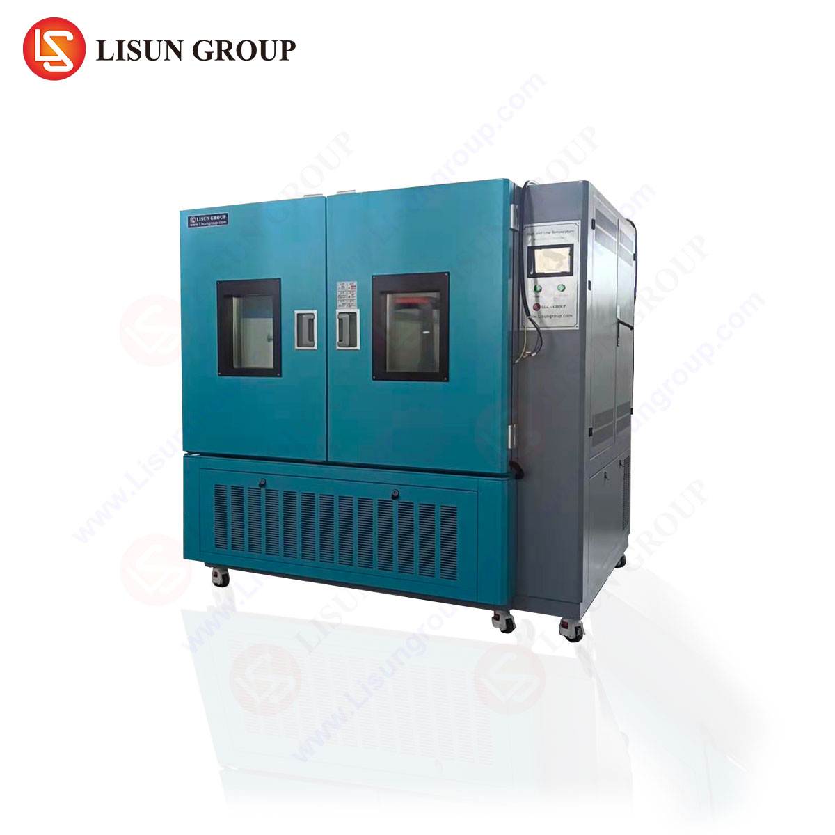
HLST-500D Thermal Shock Test Chamber: System Architecture and Operational Specifications
The LISUN HLST-500D exemplifies a two-zone (three-box) thermal shock test chamber engineered for high-throughput, high-reliability testing. Its architecture comprises three distinct sections: an elevated temperature zone, a low temperature zone, and a central basket or carriage system that transfers test specimens. This design ensures that each thermal zone remains at its setpoint, eliminating the thermal lag and recovery time associated with single-zone chambers and enabling faster transition rates.
Key Technical Specifications:
- Test Volume: 500 Liters (Internal dimensions customizable per fixture requirements).
- Temperature Range:
- High Temperature Zone: +60°C to +200°C
- Low Temperature Zone: -10°C to -65°C (extendable with optional cascade refrigeration)
- Temperature Recovery Time: ≤ 5 minutes (from +150°C to -55°C or vice versa, under full load).
- Temperature Transition Time: < 10 seconds (mechanical transfer time between zones).
- Temperature Fluctuation: ±0.5°C.
- Temperature Uniformity: ±2.0°C.
- Basket Load Capacity: 30kg (standard).
- Control System: Digital programmable controller with multi-segment profile programming, real-time graphing, and USB data logging. Compliance with key standards such as IEC 60068-2-14 (Test N: Change of temperature) and MIL-STD-883 (Method 1010.9) is inherent to its design.
The operational principle involves pre-stabilizing the UUT in one zone, followed by a rapid mechanical transfer to the opposing zone. The chamber’s programmable logic controller (PLC) manages dwell times at each extreme and the number of cycles, allowing for the precise execution of standardized test profiles or custom-developed stress screens.
Industry-Specific Applications and Failure Mode Analysis
The HLST-500D’s capability to induce high-intensity thermal mechanical stress finds critical application across a diverse spectrum of industries, each with unique failure mode concerns.
- Automotive Electronics: Electronic control units (ECUs), sensors, and infotainment systems must endure engine compartment heat and cold-soak winter conditions. Thermal shock testing validates solder joint integrity in ball grid array (BGA) packages and the resilience of conformal coatings against cracking, which could lead to latent short circuits or sensor drift.
- Aerospace and Aviation Components: Avionics, satellite components, and communication systems experience extreme temperature swings during ascent/descent or orbital cycles. Testing with the HLST-500D assesses the reliability of hermetically sealed packages and the stability of crystal oscillators, where delamination can cause catastrophic timing failures.
- Telecommunications Equipment: Base station electronics, fiber optic transceivers, and outdoor switching gear are exposed to diurnal temperature cycles. This test is vital for screening passive intermodulation (PIM) issues in connectors, which can be exacerbated by micro-movements from differential expansion.
- Medical Devices: Implantable devices and portable diagnostic equipment require absolute reliability. Thermal shock evaluates the encapsulation of batteries and the sealing integrity of housings, preventing fluid ingress or biocompatibility compromises.
- Lighting Fixtures (LED Technology): High-brightness LED assemblies are prone to failure at the die-attach and wire-bond interfaces due to coefficient of thermal expansion (CTE) mismatch. Rapid cycling accelerates this failure mechanism, allowing for the qualification of thermal management designs and materials.
- Electrical Components and PCB Assemblies: Connectors, relays, and populated printed circuit board assemblies (PCBAs) are tested for contact resistance stability and plated-through-hole (PTH) barrel cracking, which are common failure origins in field returns.
Comparative Analysis of Two-Zone Versus Single-Zone Methodologies
The selection between a two-zone chamber (like the HLST-500D) and a single-zone chamber is dictated by test requirements and standards. The two-zone system offers distinct advantages for high-rigor testing. Its primary benefit is the maintenance of setpoint stability; since each zone is dedicated, there is no need for the chamber to purge and recover temperature after each transition. This results in a consistent, severe shock at the specimen level and significantly higher testing throughput. Furthermore, it more accurately simulates certain real-world scenarios, such as a component being powered on in a cold ambient, generating immediate internal heat and a steep internal gradient.
Conversely, single-zone chambers, which alter the temperature of one workspace, can be suitable for slower transition rate tests or where footprint is a greater constraint than cycle time. However, they typically exhibit longer dwell stabilization periods and may apply a less severe thermal gradient to the UUT’s core. For compliance with stringent military, aerospace, or automotive protocols that specify maximum transition rates, the two-zone methodology is often the de facto requirement.
Integration with Broader Testing Regimes and Standards Compliance
Thermal shock testing is rarely performed in isolation. It is typically one phase within a comprehensive sequential test regimen. A common sequence involves initial performance verification, followed by thermal shock cycling, then vibration testing (often while the specimen is still thermally stressed), and concluding with final functional testing. This sequence, sometimes called “Highly Accelerated Life Testing (HALT)” or “Environmental Stress Screening (ESS),” is designed to uncover latent defects and interaction failures. The HLST-500D facilitates this integration through its programmable controller, which can be networked with other test equipment, and its robust construction, which allows the transfer basket to accommodate vibration fixtures.
Compliance with international standards is a non-negotiable aspect of chamber design. The HLST-500D is constructed to meet the parameters outlined in several critical standards:
- IEC 60068-2-14: The foundational international standard for change of temperature tests.
- MIL-STD-202G, Method 107G: For electronic and electrical component parts.
- MIL-STD-883K, Method 1010.9: For microelectronic devices.
- JESD22-A104: JEDEC standard for temperature cycling.
- Automotive OEM Specifications: Many automotive manufacturers have proprietary, derived test profiles that the chamber’s flexible programming can accommodate.
Technical Considerations for Chamber Selection and Deployment
Selecting an appropriate thermal shock chamber requires a detailed analysis of test requirements. Key decision parameters include:
- Test Specimen Volume and Mass: The 500L capacity of the HLST-500D must accommodate not only the UUTs but also any necessary mounting fixtures without impeding airflow.
- Temperature Extremes and Transition Rate: The required high and low setpoints dictate compressor and heater capacity. The specified sub-10-second transfer time is critical for achieving a true shock condition.
- Electrical Load and Signal Feed-Through: Many tests require in-situ monitoring or powering of the UUT. Chambers must be equipped with appropriate electrical ports that maintain seal integrity during transfers.
- Data Acquisition and Reporting: Integrated data logging that records chamber parameters and, ideally, allows for synchronization with external UUT monitoring data, is essential for forensic failure analysis.
- Maintenance and Calibration: The mechanical transfer system and extreme temperature operation necessitate a robust maintenance schedule. Chambers should provide accessible service points and support for regular calibration traceable to national standards.
Proper deployment involves installation in a laboratory environment with adequate electrical supply, ventilation for heat rejection, and clearance for maintenance. Operator training on safety protocols—particularly for handling extremely hot or cold surfaces and moving mechanical parts—is paramount.
Conclusion: Ensuring Reliability in an Interconnected World
As the complexity and integration of electronic and electromechanical systems continue to grow, so does the consequence of field failure. Environmental simulation chambers, particularly specialized instruments like the thermal shock test chamber, provide the empirical foundation for reliability engineering. By enabling the controlled application of extreme stresses, these tools allow designers and validation engineers to probe the boundaries of product performance, identify failure mechanisms, and implement corrective actions. The technological sophistication embodied in solutions such as the HLST-500D, with its emphasis on precision, repeatability, and standards compliance, directly contributes to the enhanced durability, safety, and longevity of products across the automotive, aerospace, telecommunications, and medical industries. In essence, they serve as a critical bridge between theoretical design and proven field-worthiness, ensuring that products are not merely functional, but resilient under the unpredictable conditions of the real world.
Frequently Asked Questions (FAQ)
Q1: What is the fundamental difference between a “thermal shock” test and a “temperature cycling” test?
The primary distinction lies in the rate of temperature change and the resultant stress applied. Thermal shock testing, as performed in a two-zone chamber like the HLST-500D, involves extremely rapid transitions (often in seconds) between temperature extremes, maximizing the thermal gradient within the unit under test. Temperature cycling typically involves slower, controlled ramps between setpoints in a single chamber. Thermal shock is more severe and is specifically targeted at inducing failures from differential expansion at material interfaces.
Q2: Can the HLST-500D chamber be used for testing powered devices, and how are electrical connections managed during the transfer between zones?
Yes, the HLST-500D can be configured for dynamic testing of powered devices. This requires the specification of electrical feed-through ports on the transfer basket. These ports utilize flexible, high-temperature/low-temperature rated cabling and specialized connectors that maintain their integrity through repeated mechanical movement and extreme temperature exposure. The test specimen remains connected to an external power supply and monitoring equipment throughout the cycling process.
Q3: How is temperature uniformity ensured within the transfer basket, especially when loaded with dense or high-thermal-mass products?
Uniformity is achieved through a combination of aerodynamic chamber design and stringent performance validation. The chamber zones feature strategically placed fans and ducting to create a consistent, high-velocity airflow around the basket. During the qualification of a new test load, sensors are placed at multiple locations on and within representative test specimens (a “mapping” study) to verify that the entire load experiences temperatures within the specified uniformity tolerance (±2.0°C for the HLST-500D). Load density and arrangement are critical factors that must be considered during test fixture design.
Q4: What standards govern the calibration of a thermal shock chamber, and what is the recommended calibration interval?
Calibration is typically performed according to guidelines such as ASTM E2877 (Standard Specification for Laboratory Chambers) or ISO/IEC 17025 for testing laboratories. The process involves mapping the temperature profile within the workspace using a multi-sensor array traceable to a national metrology institute. Key parameters verified include setpoint accuracy, uniformity, and stability. The recommended interval is annually, though more frequent checks may be required by internal quality procedures or specific customer/regulatory mandates.
Q5: For automotive testing, are there specific profiles that the HLST-500D can run to meet OEM requirements?
While many automotive OEMs have proprietary test specifications (e.g., from Ford, GM, Volkswagen), they are often derived from the core methodologies outlined in international standards like IEC 60068-2-14. The programmable controller of the HLST-500D allows engineers to create custom test profiles that define the high temperature, low temperature, dwell times at each extreme, number of cycles, and transfer parameters. This flexibility enables the chamber to be configured to meet the exacting requirements of most automotive OEM qualification tests.