


Fundamental Principles of Accelerated Environmental Stress Screening
The validation of product reliability and durability across diverse industrial sectors necessitates the simulation of extreme operational conditions within a controlled laboratory setting. Environmental test chambers serve as the cornerstone of this endeavor, enabling engineers to subject components and finished goods to precisely regulated stressors—most commonly temperature and humidity—to identify latent failures, verify design margins, and predict service life. The underlying principle is one of accelerated stress testing: by applying conditions that are more severe or rapidly cycled than those encountered in typical use, the failure modes that might manifest over months or years in the field can be observed within days or weeks. This process is critical for mitigating product recalls, reducing warranty claims, and ensuring compliance with international safety and performance standards. The data derived from such testing informs design iterations, material selection, and manufacturing processes, ultimately culminating in a more robust and dependable product portfolio.
A Comparative Analysis of Steady-State and Thermal Shock Testing Methodologies
Environmental simulation is not a monolithic discipline; it is subdivided into distinct methodologies tailored to specific failure mechanisms. Two predominant approaches are steady-state conditioning and thermal shock testing. Steady-state testing, often conducted in temperature humidity test chambers, involves maintaining a constant setpoint of temperature and relative humidity for a prolonged duration. This is instrumental in evaluating phenomena such as material creep, insulation degradation, chemical changes, and the long-term effects of moisture ingress, such as electrochemical migration on printed circuit boards (PCBs).
In contrast, thermal shock testing subjects a unit under test (UUT) to extreme, rapid transitions between hot and cold extremes. This methodology is designed to precipitate failures stemming from CTE (Coefficient of Thermal Expansion) mismatches between bonded materials, solder joint fatigue, and micro-cracking in ceramic substrates or semiconductor packages. The transition rate in a dedicated thermal shock chamber is vastly more rapid than what can be achieved in a single-zone chamber, creating mechanical stresses that are uniquely effective at identifying workmanship and design flaws. The selection between these methodologies is dictated by the product’s intended application, its material composition, and the specific reliability goals of the testing protocol.
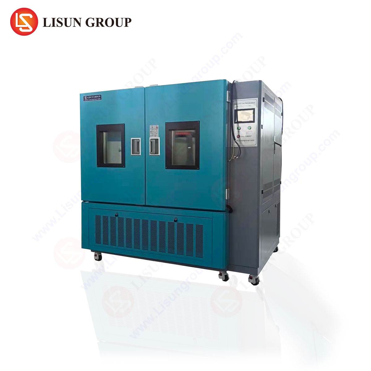
Technical Specifications and Operational Framework of the GDJS-015B Temperature Humidity Test Chamber
The LISUN GDJS-015B represents a sophisticated implementation of a benchtop temperature and humidity test chamber, engineered for high-precision stability testing. Its design incorporates a mechanically refrigerated cooling system paired with an electrical heating element and a steam humidification system to achieve a broad spectrum of conditions.
Key Performance Specifications:
- Temperature Range: -70°C to +150°C
- Humidity Range: 20% to 98% Relative Humidity
- Temperature Fluctuation: ≤±0.5°C
- Humidity Deviation: +2, -3% RH (for humidity levels above 75% RH)
- Heating Rate: Approximately 3°C per minute (ambient to +150°C under full load)
- Cooling Rate: Approximately 1°C per minute (ambient to -70°C under full load)
- Internal Volume: 100 Liters
- Controller: Digital, programmable touchscreen controller supporting ramp-and-soak profiles
The operational framework relies on a closed-loop feedback system. Platinum Resistance Thermometers (PRTs) and capacitive humidity sensors provide real-time data to the microprocessor-based controller, which modulates the compressor, heaters, and humidifier to maintain the setpoint within the stated tolerances. The chamber’s interior is typically constructed of SUS304 stainless steel for corrosion resistance, while the insulation utilizes high-density polyurethane foam to minimize thermal loss and improve temperature uniformity, which is typically maintained within ±2.0°C.
The Mechanics of Two-Zone Liquid-to-Liquid Thermal Shock via the HLST-500D
For applications requiring the most severe thermal transit rates, the two-zone liquid-to-liquid approach is employed, as exemplified by the LISUN HLST-500D Thermal Shock Test Chamber. This system operates on a fundamentally different principle than single-zone chambers, utilizing two separate liquid baths—one high temperature and one low temperature—between which a basket containing the UUT is mechanically transferred.
Key Performance Specifications of the HLST-500D:
- High Temperature Tank Range: +60°C to +200°C
- Low Temperature Tank Range: -10°C to -80°C (or ambient to -55°C)
- Recovery Time: ≤5 minutes after basket transfer (from +150°C to -55°C or vice-versa)
- Basket Transfer Time: <10 seconds
- Preheat Capacity: ≥5kg aluminum weight
- Control System: Automated, programmable controller for cycle count and dwell time management
The testing principle is one of extreme thermal flux. The UUT is immersed in the high-temperature bath until thermal saturation is achieved, then rapidly hoisted and transferred into the low-temperature bath. This transition, occurring in mere seconds, imposes a massive thermal gradient across the component’s structure. The high-temperature bath typically uses a silicone oil or other high-flash-point fluid, heated by immersion heaters. The low-temperature bath uses a mechanically refrigerated system to chill a fluid such as alcohol or a specialized silicone oil to its target. The speed of transfer and the high heat capacity of the liquid medium are what enable the extreme thermal shock conditions, making this system indispensable for qualifying components for aerospace, automotive, and high-reliability electronics applications where rapid environmental changes are expected.
Application in Electrical and Electronic Component Validation
The reliability of modern electrical systems is contingent upon the performance of their constituent components under environmental stress. The GDJS-015B chamber is extensively used for THB (Temperature Humidity Bias) testing on semiconductors, capacitors, and connectors. By applying elevated temperature (e.g., 85°C) and high humidity (85% RH) while simultaneously biasing the component with an electrical load, manufacturers can accelerate the growth of conductive anodic filaments (CAF) between PCB traces and identify moisture-resistant weaknesses in encapsulation materials. For automotive electronics, such as engine control units (ECUs), chambers are used to validate operation across the full SAE J1455 specified temperature range, ensuring functionality from frigid cold starts to under-hood peak temperatures.
Assessing Durability in Automotive and Aerospace Subassemblies
In the automotive and aerospace sectors, components must endure not only wide temperature swings but also rapid changes. The HLST-500D thermal shock chamber is critical for testing these subsystems. An automotive LED headlamp assembly, for instance, incorporates a metal heat sink, plastic housing, glass or polycarbonate lens, and numerous solder joints. Repeated thermal cycling from -40°C (simulating a winter night) to +105°C (simulating operation near a hot engine) can cause delamination, lens fogging, or solder fracture. Thermal shock testing accelerates this failure process. Similarly, in aerospace, avionics modules are subjected to shock tests that simulate the temperature extremes between being on the ground in a cold climate and the heat generated at high-altitude operation, ensuring integrity and preventing failure due to CTE mismatches in the module’s construction.
Material and Coating Performance Under Cyclic Hygrothermal Conditions
Beyond electronic failures, environmental chambers are vital for assessing the physical and chemical stability of materials and protective coatings. Household appliances, such as washing machine control panels or refrigerator compressor housings, are tested in humidity chambers to evaluate resistance to corrosion, UV stability (when combined with a light source), and the propensity for mold growth. The gloss retention, color fastness, and adhesion of painted or powder-coated surfaces on office equipment and consumer electronics are rigorously tested using cyclic conditions that alternate between high humidity and dry heat, replicating years of indoor environmental exposure in a matter of weeks.
Compliance with International Testing Standards and Protocols
The use of environmental chambers is often not optional but mandated by a complex framework of international standards. Reproducible testing requires strict adherence to these protocols, which define parameters such as ramp rates, dwell times, and tolerances. Key standards referenced include:
- IEC 60068-2-1 & 2: Basic environmental testing procedures for cold and dry heat.
- IEC 60068-2-30: Damp heat, cyclic (12h + 12h cycle).
- IEC 60068-2-14: Change of temperature tests.
- MIL-STD-810H: Environmental engineering considerations and laboratory tests, widely used in aerospace and defense.
- JESD22-A104: Temperature cycling, from the JEDEC Solid State Technology Association.
- ISO 16750-4: Road vehicles — Environmental conditions and testing for electrical and electronic equipment — Part 4: Climatic loads.
Chambers like the GDJS-015B and HLST-500D are designed and validated to meet or exceed the requirements stipulated in these documents, providing manufacturers with certified evidence of compliance for regulatory submissions and customer audits.
Critical Selection Criteria for Environmental Test Equipment
The procurement of an environmental chamber is a significant capital investment, and its selection must be guided by a clear understanding of technical and operational requirements. Key criteria include:
- Test Requirements: The temperature and humidity ranges, as well as the required transition rates (for cycling tests), must be the primary drivers. A steady-state humidity chamber cannot replicate the transfer speed of a dedicated thermal shock unit.
- Chamber Volume and Load: The internal workspace must accommodate the UUT and any associated fixtures without obstructing airflow, which is critical for uniformity. The thermal mass of the product load directly impacts the chamber’s ability to meet specified ramp rates.
- Control and Data Logging: The controller must be capable of executing complex multi-segment profiles. Sufficient data logging resolution and sampling rates are necessary to provide a verifiable test record.
- Construction and Safety: Chamber construction materials must be compatible with the test conditions. Safety features, such as independent overtemperature protection, coolant failure alerts, and proper grounding, are non-negotiable.
- Total Cost of Ownership: Beyond the initial purchase price, considerations for utility consumption (electrical power, water for humidification, liquid nitrogen for rapid cooling), preventive maintenance costs, and serviceability are crucial for long-term operational budgeting.
Frequently Asked Questions
Q1: What is the fundamental difference between temperature cycling and thermal shock testing?
Temperature cycling typically occurs in a single chamber where the air temperature is ramped up and down at a controlled rate, often a few degrees Celsius per minute. Thermal shock testing utilizes a two-station system (either two air chambers or two liquid baths) to achieve an extremely rapid transfer, subjecting the product to a temperature change rate that can exceed 30°C per minute, thereby inducing different and often more severe mechanical stresses.
Q2: Why is the recovery time specification critical in a thermal shock chamber?
Recovery time refers to the duration required for the chamber’s medium (air or liquid) to return to its setpoint temperature after the test basket, which is at the opposite extreme temperature, has been introduced. A short recovery time (e.g., ≤5 minutes for the HLST-500D) is essential because it ensures the UUT is exposed to the full intended temperature extreme for the vast majority of the designated dwell time, maintaining the test’s severity and validity.
Q3: Can a standard temperature humidity chamber like the GDJS-015B be used for burn-in testing of electronic assemblies?
Yes, absolutely. Burn-in testing is designed to precipitate early-life failures (infant mortality) by operating devices at elevated temperatures, often with electrical bias applied. The GDJS-015B is well-suited for this task, as it can maintain a stable elevated temperature (e.g., 125°C for ICs) for extended periods. Combining this with humidity allows for more comprehensive stress conditions, simulating harsh operational environments.
Q4: What are the primary factors that influence the ramp rate specifications of a test chamber?
The achievable ramp rate is not an intrinsic property of the chamber alone but a function of the chamber’s thermal capacity (heating power and refrigeration capacity), the thermal mass of the product load inside, and the chamber’s internal air-flow dynamics. A chamber’s published ramp rate is typically measured empty; a significant product load will invariably reduce the actual performance.
Q5: For testing telecommunications equipment intended for outdoor use, which standards are most relevant, and which chamber type is appropriate?
Telecom equipment is often tested against standards like Telcordia GR-63-CORE (NEBS) and IEC 60721-3-xx, which define classes for stationary use at weather-protected and non-weather-protected locations. These tests involve combined temperature and humidity cycles, often with low-temperature operational tests. A high-performance temperature humidity chamber like the GDJS-015B, with its wide temperature range (-70°C to +150°C) and precise humidity control, is the appropriate tool for validating product against these requirements.