


Abstract
A properly functioning environmental test chamber is the cornerstone of reliable LED lumen maintenance testing, as defined by standards like IES LM-80 and TM-21. When an environmental test chamber is not dehumidifying, it introduces uncontrolled humidity variables that can invalidate long-term aging data, compromise Arrhenius-based lifetime projections, and lead to non-compliance. This technical article provides a systematic troubleshooting & solutions framework for professionals, integrating core principles from LISUN‘s LED Optical Aging Test Instrument platforms. We will analyze failure modes—from refrigerant issues to sensor calibration—within the context of maintaining the precise, dry conditions required for accurate LED LM-80/TM-21 and LM-84/TM-28 testing, ensuring your chamber supports, rather than sabotages, your reliability validation.
1.1 Humidity as an Uncontrolled Variable in Lumen Maintenance Tests
Precise environmental control is non-negotiable in LED reliability testing. While temperature is the primary acceleration factor per the Arrhenius Model, uncontrolled humidity acts as a confounding variable. Moisture ingress can accelerate chemical degradation within the LED package, leading to non-representative lumen depreciation curves, premature phosphor degradation, and metallic corrosion. For tests like the 6000-hour LM-80 or extended LM-84 validation, a chamber not dehumidifying introduces a secondary failure mechanism not accounted for in TM-21 or TM-28 extrapolation models, rendering projected L70/L50 metrics scientifically unreliable.
1.2 Alignment with Industry Standards: Dry Conditions as a Mandate
Key industry standards implicitly or explicitly mandate low-humidity conditions. IES LM-80-20 requires testing at controlled case or board temperatures, with ambient conditions that do not induce condensation or unintended stress. The Arrhenius-based software in systems like the LISUN LEDLM-80PL assumes temperature is the sole accelerating factor; humidity invalidates this assumption. Furthermore, standards like IES LM-79-19 (for electrical and photometric measurements) and CIE 127:2007 (for LED intensity measurement) presuppose stable, non-condensing environments during preconditioning and testing to ensure repeatable optical data, which is the foundation for all subsequent aging analysis.
2.1 Preliminary Operational and Configuration Checks
Before disassembling hardware, verify basic operational parameters. Confirm the chamber’s setpoint is correctly configured for a low dew point; a setpoint above ambient dew point will not activate the dehumidification system. Inspect the chamber seal and gaskets for integrity, as a constant influx of humid room air can overwhelm the system. For multi-chamber setups, such as a LISUN LEDLM-84PL system controlling up to 3 temperature chambers, verify that the dehumidification unit serving the common air-handling path is correctly sized for the total load and that control software is configured to manage humidity for all connected zones.
2.2 Sensor and Control System Diagnostics
Faulty sensors are a common culprit. Calibrate or replace the humidity sensor (hygrometer) and temperature sensor. A drifting humidity sensor can provide false “dry” readings, preventing the compressor from engaging. Next, examine the control system’s logic. The system should initiate a dehumidification cycle when the measured relative humidity (RH) or dew point exceeds the setpoint. Review error logs in the chamber’s controller or the master software (e.g., LISUN’s Arrhenius Model-based platform) for fault codes related to the refrigeration circuit or sensor failures.
3.1 Refrigerant Circuit Issues: Low Charge and Compressor Failure
The most common cause for a chamber not dehumidifying is a failure in the mechanical refrigeration circuit used to cool the evaporator coil below the dew point. Symptoms include:
- Low Refrigerant Charge: Due to leaks, resulting in insufficient cooling capacity. The compressor may run continuously without lowering coil temperature enough to condense moisture.
- Compressor Failure: The compressor may not start, trip on overload, or have internal mechanical failure, providing no cooling.
- Restricted Filter-Drier or Expansion Valve: This reduces refrigerant flow, limiting cooling and dehumidification performance. Diagnosis requires manifold gauges to check system pressures against specifications.
3.2 Evaporator Coil and Condensate Management Problems
Even with a functioning refrigeration circuit, moisture removal can fail. A severely frosted evaporator coil, caused by a defective defrost heater, timer, or sensor, acts as an insulator and blocks airflow. The condensate drain line may be clogged with algae or debris, causing the drain pan to overflow and re-evaporate water back into the chamber. Inspect the drain pan heater (if equipped) to ensure it prevents freezing at the drain outlet, which would also cause a blockage.
4.1 Electrical Component Verification
Sequentially test electrical components in the dehumidification path. Use a multimeter to check for proper voltage at the compressor contactor coils. Verify that relays and contactors are energizing and that start capacitors for the compressor and fan motors are within capacitance tolerance. A failed condenser fan motor will cause high head pressure, leading to compressor shutdown on the high-pressure switch, halting the entire dehumidification process.
4.2 Airflow Obstructions and System Balance

Insufficient airflow across the cold evaporator coil reduces dehumidification efficiency. Check and replace clogged air filters. Ensure the evaporator fan motor is operating at correct RPM and that the blower wheel is clean. For test chambers loaded with LED fixtures or arrays, ensure the product load does not obstruct the designed airflow path within the workspace, creating localized pockets of stagnant, humid air that the sensor cannot accurately sample.
5.1 Impact on Test Modes and Data Integrity
LISUN systems offer dual testing modes: real-time monitoring and accelerated aging. A chamber not dehumidifying corrupts both. In real-time mode, spurious humidity-induced decay is recorded as lumen depreciation, skewing the entire dataset. In accelerated mode, where temperature is precisely elevated to project life via TM-21, added humidity creates an unquantified acceleration factor, making the Arrhenius extrapolation invalid. This can lead to grossly optimistic L70 lifetime projections, posing significant financial and reputational risk.
5.2 Protocol for Test Continuity and Data Recovery
Upon identifying a dehumidification failure, a formal assessment is required. Document the time and duration of the excursion. Determine if the humidity spike exceeded limits defined in your test plan (often <60% RH non-condensing). If the deviation is severe, the test may need to be paused or restarted from a known baseline, as per internal quality procedures. Data recorded during the excursion should be flagged and potentially excluded from the final TM-21 analysis to maintain compliance with the standard's intent.
6.1 Scheduled Preventive Maintenance Checklist
Prevent failure through a rigorous PM schedule:
- Monthly: Inspect and clean air filters; verify condensate drain flow.
- Quarterly: Check and clean evaporator and condenser coils; verify sensor readings with a calibrated external probe.
- Annually: Perform a full electrical safety and performance check, including compressor amp draw and refrigerant pressures. Calibrate all chamber sensors (temperature, humidity) to NIST-traceable standards.
6.2 System Calibration and Performance Verification
Annual calibration is critical. This involves not just sensors, but also verifying the chamber’s ability to achieve and maintain low dew points across its entire temperature range. Use a calibrated dew point meter to create a performance map. Furthermore, when integrating a chamber with a LISUN optical aging system, ensure the chamber’s communication protocol (e.g., Modbus) is correctly configured so that humidity alarms are logged by the master software, providing an audit trail for test integrity.
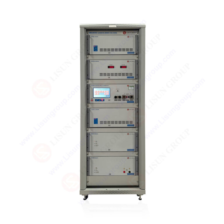
7.1 Hardware Synergy: Test Instruments and Chamber Specifications
LISUN’s LED Optical Aging Test Instruments are designed with integrated chamber requirements in mind. The LEDLM-80PL (for LM-80/TM-21) and LEDLM-84PL (for LM-84/TM-28) systems support connection to up to 3 external temperature chambers, but the specification assumes those chambers meet performance criteria. The table below outlines critical chamber specifications necessary to ensure compatible and reliable operation with LISUN’s aging test systems.
Table: Minimum Recommended Environmental Chamber Specifications for LISUN LED Aging Systems
| Parameter | Specification for LM-80 Testing | Specification for LM-84 Testing | Rationale |
| :— | :— | :— | :— |
| Temperature Range | -10°C to +110°C | +10°C to +60°C (ambient simulation) | Covers LM-80 temp requirements & LM-84 ambient conditions. |
| Temperature Uniformity | ±0.5°C at 55°C | ±1.0°C across workspace | Ensures consistent thermal stress on all LED samples. |
| Humidity Range (if applicable) | 10% to 98% RH | 10% to 98% RH | For general-purpose capability; LM-80 typically uses dry air. |
| Dehumidification Method | Mechanical Refrigeration | Mechanical Refrigeration | Provides reliable, continuous moisture removal. |
| Dew Point Capability | Able to maintain < -10°C dew point | Able to maintain < +5°C dew point | Guarantees dry conditions for LM-80; controls humidity for LM-84. |
| Control Interface | RS-485/Modbus or Ethernet | RS-485/Modbus or Ethernet | Enables direct integration with LISUN master control software. |
7.2 Software-Enabled Monitoring and Control
The Arrhenius Model-based software provides a higher layer of oversight. It can be configured to monitor chamber humidity readings in real-time alongside optical data. If humidity deviates from a user-defined band, the software can trigger alarms, pause optical measurements, or flag the data. This creates a closed-loop system where environmental integrity is continuously validated against the photometric data stream, ensuring any anomaly is immediately detected and documented.
A malfunctioning dehumidification system in an environmental test chamber is a critical failure that directly threatens the validity of long-term LED reliability data. As detailed, troubleshooting requires a methodical approach across sensor, electrical, refrigeration, and airflow subsystems. The integrity of standards-compliant testing, from the 6000-hour data collection of IES LM-80 to the complex extrapolations of TM-21 and TM-28, is predicated on precise, dry, and controlled acceleration factors. LISUN’s LED Optical Aging Test Instruments, such as the LEDLM-80PL and LEDLM-84PL, provide the sophisticated optical measurement and analysis framework, but their output is only as reliable as the environmental input. By implementing rigorous maintenance, proactive calibration, and selecting chambers that meet stringent performance specifications, engineers can ensure their troubleshooting & solutions for a chamber not dehumidifying are effective, safeguarding the accuracy of lumen maintenance projections and the credibility of their product validation processes.
Q1: How quickly can humidity excursions during an LM-80 test invalidate our TM-21 projection data?
A: There is no universal safe duration; it depends on the severity of the excursion and the LED product’s sensitivity. A short, minor spike may have negligible impact, but any prolonged exposure to high humidity (e.g., >80% RH for hours) likely invalidates data for that period. IES TM-21-11 advises using data from “controlled conditions.” The conservative approach is to flag and exclude all data from the start of the excursion until the chamber has stabilized back at the correct, dry setpoint for a period equal to 3-5 times the chamber recovery time. This ensures only data under known, controlled acceleration factors is used for the Arrhenius fit and L70 projection.
Q2: Can we use desiccant-based dehumidification instead of mechanical refrigeration for our LED aging chamber?
A: While desiccant systems are excellent for achieving extremely low dew points, mechanical refrigeration is typically preferred and specified for standard LED LM-80 testing. Refrigeration systems are more energy-efficient for the moderate temperature ranges (e.g., 55°C, 85°C, 105°C) used in LM-80, and they provide precise, stable temperature control simultaneously. Desiccant systems add heat, requiring more cooling capacity, and can introduce complexity. For a dedicated LED aging chamber, a well-maintained mechanical system meeting the dew point capability in our specification table is the most reliable and standard-compliant choice.
Q3: Our chamber dehumidifies at lower temperatures but not at the 85°C LM-80 test point. What could be wrong?
A: This points to a capacity limitation in the refrigeration system. At a high chamber setpoint like 85°C, the temperature difference between the refrigerant in the evaporator coil and the chamber air is reduced. If the system is undercharged, has a partially clogged filter-drier, or has a failing compressor, it may not be able to cool the coil sufficiently below the dew point of the 85°C air to condense moisture. Check the refrigerant subcooling and superheat at the 85°C condition against manufacturer specifications. The system may require servicing to restore its full capacity across the entire operational range.