


The Role of Environmental Thermal Chambers in Product Validation and Reliability Engineering
Environmental thermal chambers represent a cornerstone of modern product validation, providing the controlled climatic conditions necessary to simulate the stresses of real-world operation within a laboratory setting. These sophisticated instruments are indispensable for uncovering latent design flaws, verifying material performance, and ensuring long-term reliability across a vast spectrum of industries. By precisely manipulating temperature and humidity, engineers can accelerate the aging process, identify failure mechanisms, and substantiate product durability long before deployment in the field. The data derived from such testing protocols directly informs design iterations, mitigates warranty risks, and underpins compliance with international standards, making environmental simulation not merely a testing step but a critical component of the product development lifecycle.
Fundamental Principles of Climatic Stress Testing
The underlying principle of environmental testing is the application of thermodynamic and materials science to emulate the effects of environmental exposure. All materials exhibit coefficients of thermal expansion, and electronic components possess operational temperature ranges defined by their semiconductor properties. When subjected to thermal cycling, differing expansion rates between bonded materials—such as a silicon die and its substrate—induce mechanical stress, potentially leading to solder joint fatigue, delamination, or cracked interconnects. The introduction of humidity, particularly when combined with temperature transitions, can lead to condensation, which acts as a catalyst for electrochemical migration, dendritic growth, and corrosion. A thermal chamber’s primary function is to apply these stresses in a controlled, repeatable, and accelerated manner. The chamber must achieve and maintain specified setpoints with high fidelity, ensuring that the stress applied to the unit under test (UUT) is precisely defined and not a byproduct of equipment instability. The rate of temperature change, or ramp rate, is a critical parameter, as more rapid transitions often induce greater mechanical strain, thereby providing a more stringent assessment of a product’s robustness.
Analyzing the GDJS-015B Temperature Humidity Test Chamber
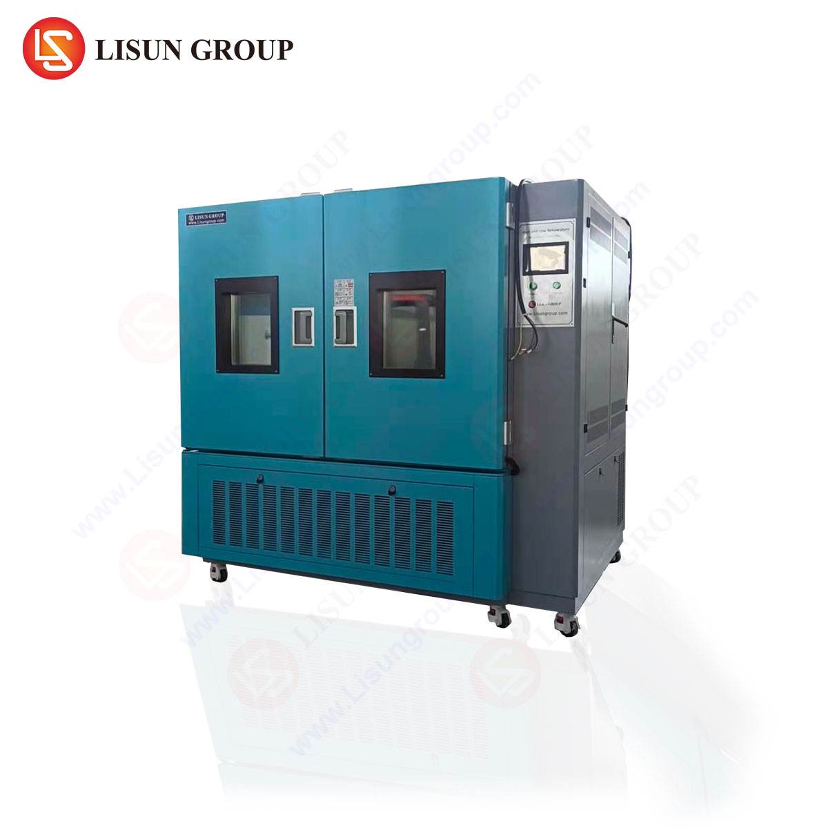
The LISUN GDJS-015B temperature humidity test chamber is engineered to deliver precise and stable control over a broad spectrum of climatic conditions. Its design philosophy centers on creating a homogeneous testing environment to ensure that the UUT is subjected to uniform stress, thereby yielding reliable and reproducible data.
Key Specifications:
- Temperature Range: -70°C to +150°C
- Humidity Range: 20% to 98% Relative Humidity
- Temperature Fluctuation: ≤±0.5°C
- Humidity Fluctuation: ≤±2.5%
- Heating Rate: Approximately 3°C/min (ambient to +150°C, under full load)
- Cooling Rate: Approximately 1°C/min (ambient to -70°C, under full load)
Testing Principles and System Architecture:
The chamber utilizes a cascade refrigeration system to achieve its extended low-temperature range. A high-stage compressor manages the heat load from ambient down to approximately -40°C, at which point a low-stage compressor takes over to reach the ultimate temperature of -70°C. This configuration ensures efficient operation and prevents single-stage overloading. For humidity generation, a boiler system produces pure, steam-based humidity, avoiding the mineral contamination associated with atomizing systems. A dehumidification system, often integrated within the refrigeration circuit, allows for precise control of low humidity setpoints. The chamber’s inner chamber is typically constructed from SUS304 stainless steel, chosen for its corrosion resistance and thermal stability, while high-density glass wool insulation minimizes thermal loss and improves temperature uniformity, which is typically within ±2.0°C.
Application of Steady-State and Cyclic Environmental Stresses
The GDJS-015B facilitates a wide array of test profiles, from steady-state dwells to complex cyclic regimens. A common steady-state application is high-temperature operating life (HTOL) testing for integrated circuits, where components are powered and monitored for extended periods at elevated temperatures (e.g., 125°C) to accelerate failure rates and project mean time between failures (MTBF). Conversely, low-temperature storage tests assess material brittleness and lubricant performance in automotive electronics destined for cold-climate markets.
Cyclic testing is more representative of real-world conditions where products experience daily and seasonal fluctuations. A typical temperature-humidity bias (THB) test, crucial for microelectronics and automotive control units, involves cycling between 85°C/85% RH and lower setpoints while the device is electrically biased. This combination of thermal expansion and contraction with the presence of an electrical potential aggressively promotes failure mechanisms like electrolytic corrosion and conductive anodic filament (CAF) formation in printed circuit boards (PCBs). For consumer electronics and lighting fixtures, cyclic tests simulate the internal heat generation during operation followed by cooling during standby, testing the resilience of solder joints, connectors, and housing materials to repeated stress.
The Mechanism of Thermal Shock Testing and the HLST-500D
While the GDJS-015B excels at controlled ramps, some failure modes are triggered specifically by extreme, rapid temperature transitions. Thermal shock testing, also known as temperature cycling or thermal stress testing, subjects a product to instantaneous transfers between hot and cold extremes. This test is designed to identify weaknesses in assemblies comprising materials with dissimilar coefficients of thermal expansion (CTE).
The LISUN HLST-500D thermal shock test chamber is a three-zone system (high-temperature zone, low-temperature zone, and a moving basket that houses the UUT) built for this exact purpose. The basket rapidly transfers test samples between the two extreme temperature zones, minimizing transition time and maximizing the thermal stress imposed.
Key Specifications:
- High-Temperature Range: +60°C to +200°C
- Low-Temperature Range: -10°C to -65°C
- Recovery Time: ≤5 minutes (from +150°C to -55°C or vice-versa, after specimen transfer)
- Preheat and Pre-cool Time: ≤30 minutes
- Test Station Capacity: Standard configuration for a defined load
- Basket Transfer Time: <10 seconds (manual or automatic)
Testing Principles and Failure Mechanisms:
The HLST-500D’s efficacy lies in its ability to induce a high rate of temperature change. The chamber’s hot and cold zones are maintained at their target temperatures, ready to receive the test basket. The rapid transfer, often accomplished via a vertical elevator or horizontal carriage system, exposes the UUT to a near-instantaneous change in ambient temperature. This creates immense shear stress at material interfaces. Common failure sites include BGA (Ball Grid Array) solder balls, wire bonds in semiconductor packages, and the plated-through holes in multi-layer PCBs. For aerospace and aviation components, which must endure the extreme temperature differentials between ground operation and high-altitude flight, thermal shock testing is a mandatory validation step. The HLST-500D’s fast recovery time ensures that the chamber zones quickly return to setpoint after the thermal mass of the basket is introduced, maintaining the integrity of the test profile throughout its duration.
Industry-Specific Validation Protocols and Use Cases
The application of environmental thermal chambers is dictated by the unique reliability requirements of each industry sector.
Automotive Electronics: Components like engine control units (ECUs), sensors, and infotainment systems are tested against standards such as ISO 16750-4. This involves thousands of cycles between -40°C and +125°C in chambers like the GDJS-015B to simulate a vehicle’s lifetime of exposure. Thermal shock testing with the HLST-500D is used to validate the robustness of under-hood electronics against sudden temperature changes, for instance, when a cold engine is started in a winter environment.
Telecommunications Equipment: Base station electronics, routers, and switches are subjected to high-temperature, high-humidity tests (e.g., 85°C/85% RH for 1,000 hours) to ensure signal integrity and prevent corrosion-induced failures. The pure steam humidity system of the GDJS-015B is critical here to avoid contaminant-related failures.
Medical Devices: Reliability is paramount. Implantable devices undergo stringent thermal cycling to ensure hermeticity, while diagnostic equipment like MRI machines and patient monitors are tested for stability across operating room environments. Standards like IEC 60601-1 specify climatic requirements that can be validated using these chambers.
Aerospace and Aviation Components: These components face the most extreme environmental swings. Testing per DO-160 or MIL-STD-810 involves thermal shock profiles that the HLST-500D is designed to execute, moving components from a cold soak at -65°C to a high-temperature exposure exceeding +100°C in seconds.
Lighting Fixtures and Consumer Electronics: LED drivers and luminaires are cycled to test for premature lumen depreciation and color shift. The thermal management of modern consumer electronics, such as smartphones and laptops, is validated through cycles that simulate internal heating and external environmental cooling, ensuring that casings, batteries, and internal connections do not fail.
Electrical Components and Cable Systems: Switches, sockets, and wiring harnesses are tested for insulation integrity, contact resistance, and physical durability. A GDJS-015B can simulate years of seasonal variation to ensure a cable’s polymer jacket does not become brittle in the cold or soften excessively in the heat, preventing cracking or deformation.
Comparative Advantages in Chamber Selection and Operation
Selecting the appropriate chamber is a critical decision. The GDJS-015B, with its broad temperature and humidity range and controlled ramp rates, is the versatile workhorse for the majority of development and qualification testing. Its key advantage lies in its precision and stability, which are non-negotiable for accurate lifetime predictions and standards compliance. The use of a cascade refrigeration system and steam humidification represents a design choice that prioritizes performance and sample integrity over mere cost.
In contrast, the HLST-500D thermal shock chamber is a specialized tool. Its competitive advantage is its speed and the severity of the stress it applies. The fast transfer time and minimal recovery period are engineered to maximize the ΔT/Δt (rate of temperature change over time), making it exceptionally effective at precipitating latent mechanical defects that more gradual tests might miss. For industries where product failure carries significant safety or financial risk—such as aerospace, automotive, and medical—the ability to uncover these specific failure modes early is invaluable.
Operational considerations also differ. A thermal shock test is typically shorter in duration but more intense, while a temperature-humidity cycle test can run for hundreds or thousands of hours. The data acquisition requirements also vary; thermal shock tests often rely on functional testing at temperature extremes, while long-duration tests may require continuous in-situ monitoring of electrical parameters.
Frequently Asked Questions (FAQ)
Q1: What is the critical difference between a temperature humidity test chamber and a thermal shock test chamber?
The primary difference lies in the rate of temperature change. A temperature humidity chamber, like the GDJS-015B, provides controlled ramp rates to simulate gradual environmental shifts and allows for humidity control. A thermal shock chamber, like the HLST-500D, achieves near-instantaneous transfers between pre-heated and pre-cooled zones to induce extreme mechanical stress, typically without active humidity control during the transition. The test objective dictates the choice: gradual aging versus revealing assembly and material interface weaknesses.
Q2: Why is the humidity system in the GDJS-015B based on a steam generator rather than an atomizing system?
Steam generation using purified water prevents the introduction of minerals and impurities into the test chamber’s atmosphere. Atomized water droplets contain dissolved solids that can settle on the unit under test, leading to conductive contamination, electrolytic leakage currents, and false failure indications, particularly on sensitive electronic assemblies. The steam method ensures a clean, controllable humidity source, which is essential for valid and reliable test outcomes in electronics validation.
Q3: How is the transfer time defined and verified in a thermal shock test chamber like the HLST-500D?
Transfer time is formally defined in standards like MIL-STD-883 and JESD22-A104 as the duration the test sample spends in transit between the two temperature zones. It is typically measured from the moment the chamber door begins to open until it is fully closed at the destination zone. This time is kept to an absolute minimum (e.g., <10 seconds for the HLST-500D) to prevent the sample from experiencing an uncontrolled temperature profile. Verification is performed using a high-speed data logger with thermocouples attached to a dummy load representative of the actual test specimens.
Q4: For a new product, how does an engineer determine the appropriate test profile (temperature range, cycle count, dwell times)?
The test profile is derived from a combination of sources. Firstly, relevant industry standards (e.g., IEC, ISO, MIL-STD) provide standardized profiles for specific product categories. Secondly, the product’s intended operational environment is analyzed—for example, an automotive component’s profile will be based on under-hood temperature data. Finally, accelerated life testing models are used, where the stress levels are increased to precipitate failures in a shorter time, and the results are extrapolated to normal operating conditions using established models like the Arrhenius equation for temperature or the Peck model for temperature-humidity effects.
Q5: Can a thermal shock test be performed in a single-zone temperature chamber?
No, a valid thermal shock test cannot be conducted in a standard single-zone chamber. The fundamental requirement is the rapid exposure of the test specimen to two extreme, stable temperature environments. A single-zone chamber can only ramp between temperatures, which results in a much slower rate of change and a fundamentally different, less severe type of thermal stress. The two-zone (or three-zone) architecture of a dedicated thermal shock chamber is essential to achieve the required thermal transient.