


Comprehensive Methodologies for Fire Hazard Assessment in Modern Electronic Components
The proliferation of complex electronic systems across diverse industries has necessitated a rigorous and scientific approach to evaluating fire hazards. The potential for a small internal electrical fault to escalate into a catastrophic fire event represents a critical failure mode with implications for safety, liability, and brand integrity. Fire hazard assessment, therefore, is not a singular test but a systematic philosophy of identifying ignition sources, evaluating material flammability, and verifying the containment capabilities of components and enclosures. This analytical process is fundamental to the design, certification, and manufacturing of safe products, from everyday household appliances to mission-critical aerospace systems.
The Combustion Triangle and Ignition Sources in Electronic Systems
At the core of any fire hazard analysis lies the fundamental principle of the fire triangle: for combustion to occur, a fuel source, an oxidizer (typically atmospheric oxygen), and an ignition source must be present simultaneously. In the context of electronic equipment, the fuel is often the polymeric materials used for insulation, enclosures, and circuit boards. The oxidizer is the ambient air. The ignition source, however, can be multifaceted and notoriously difficult to predict entirely. Common electrical ignition sources include:
- Overcurrent Conditions: Excessive current flow through conductors or components, such as semiconductors or connectors, can generate resistive (I²R) heating sufficient to reach the auto-ignition temperature of adjacent materials.
- Arc Faults: Unintended arcs can occur due to damaged wiring, loose connections, or component failure. These arcs possess extremely high localized temperatures, often exceeding 3000°C, capable of instantly vaporizing and igniting most organic materials.
- Glowing Connections: Loose mechanical connections, such as a poorly seated wire in a terminal block, can create a point of high electrical resistance. This point may heat to a incandescent glow without tripping conventional overcurrent protection, providing a persistent and potent ignition source.
- Component Failure: The catastrophic failure of components like resistors, capacitors, or integrated circuits can release significant thermal energy, molten metal, or flaming particles.
The primary objective of fire hazard assessment is to break the combustion triangle by designing products that either eliminate potential ignition sources or, more pragmatically, ensure that if an ignition occurs, it is not self-sustaining and is contained within the component or enclosure.
Simulating Real-World Fault Conditions with the Needle Flame Test
While many standardized tests evaluate material flammability under controlled laboratory conditions (e.g., UL 94, IEC 60695-11-10), they do not fully replicate the threat posed by small, persistent flames arising from internal faults. A failing small capacitor, a glowing connection, or an overheated section of a printed circuit board can produce a flame of limited energy and duration. The critical question is whether this small, localized flame can propagate to other parts of the apparatus.
The needle flame test is engineered specifically to answer this question. It simulates the thermal stress effect of such small flames that may result from fault conditions within electrical equipment. The test provides a means to assess the fire hazard by applying a defined small flame to a test specimen under controlled laboratory conditions, observing the subsequent burning and spreading behavior, and evaluating the ability of the product to contain the fire.
The test is governed by the international standard IEC 60695-11-5, “Fire hazard testing – Part 11-5: Test flames – Needle-flame test method – Apparatus, confirmatory test arrangement and guidance.” This standard meticulously defines the test apparatus, the flame characteristics, the calibration procedure, and the criteria for assessing test results. Compliance with this test is a mandatory requirement in the safety certification of a vast range of products across numerous sectors.
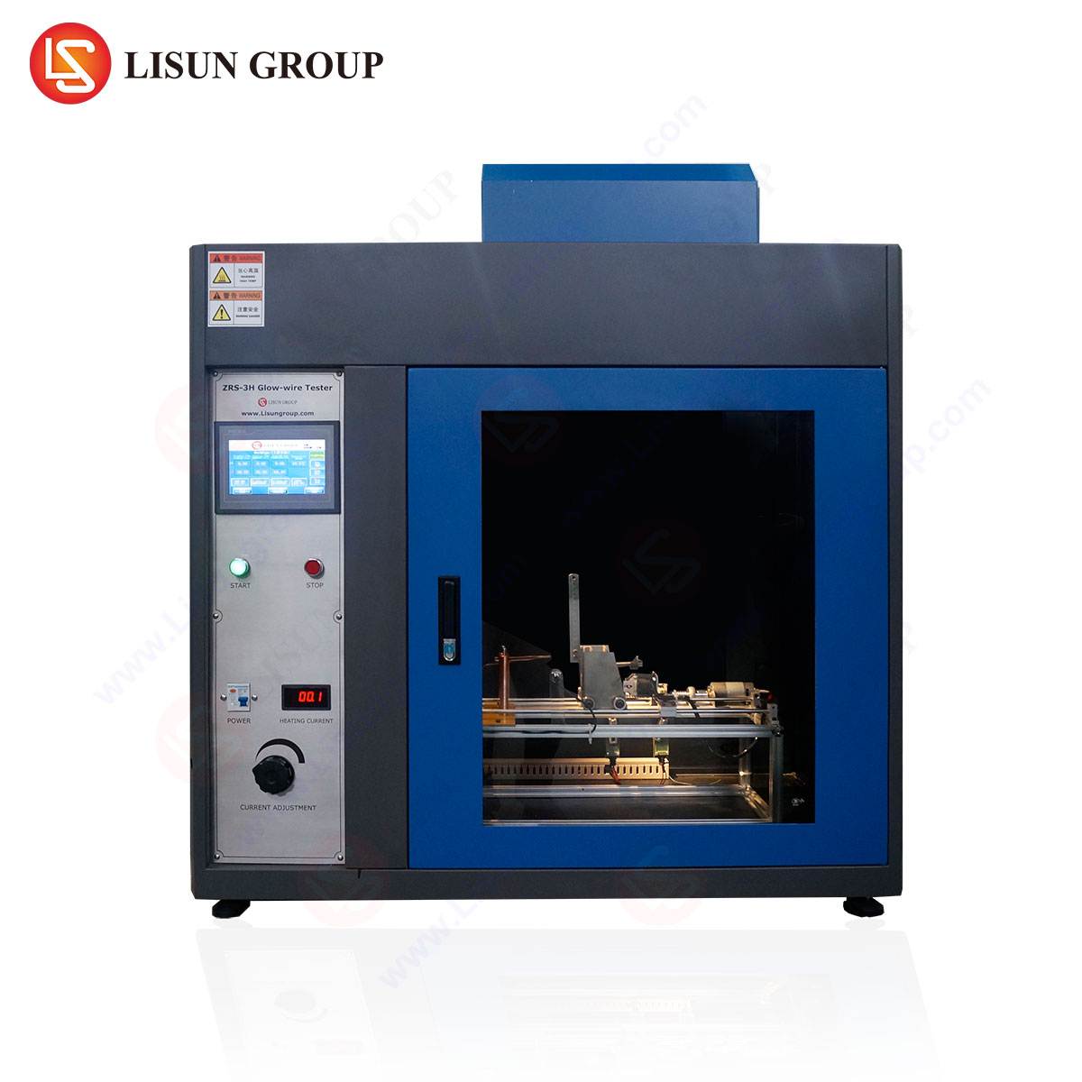
Technical Specifications and Operational Principles of the LISUN ZY-3 Needle Flame Test Apparatus
The LISUN ZY-3 Needle Flame Test Apparatus represents a state-of-the-art implementation of the requirements set forth in IEC 60695-11-5. Its design prioritizes precision, repeatability, and user safety, providing reliable data for engineering and certification purposes.
Key Technical Specifications:
- Needle Diameter: Ø0.9mm ± 0.05mm, conforming to the standard’s requirement for a consistent and reproducible flame source.
- Flame Application Time: Programmable from 0 to 999.9 seconds, with an accuracy of ±0.1%, allowing for precise simulation of various fault durations.
- Flame Height: Adjustable from 12mm ± 2mm, calibrated using a proprietary gauge to ensure conformity before each test session.
- Fuel: Technical-grade butane gas with a specified minimum purity of 95%, ensuring consistent calorific output and flame characteristics.
- Timing Control: Fully automated ignition, timing, and retraction sequence, eliminating operator-dependent variables and enhancing test reproducibility.
- Construction: The apparatus is constructed with a stainless-steel main body and incorporates a transparent polycarbonate enclosure. This design contains any potential burning debris while allowing for unobstructed observation and high-speed video recording of the test in progress.
- Safety Features: Integrated gas leak detection and automatic shut-off valves mitigate operational hazards.
Testing Principle and Procedure:
The operational principle of the ZY-3 is based on a rigorously controlled application of a small flame. The procedure is as follows:
- Calibration: Prior to testing, the apparatus is calibrated. The needle flame is ignited and adjusted to a height of 12mm. The temperature of the flame is verified by a thermocouple positioned at a specific distance; the flame must achieve a temperature of 1000°C ± 50°C within a set time frame.
- Specimen Preparation: The test specimen—which could be a complete end-product, a sub-assembly, a mock-up, or a section of material—is mounted in a representative orientation, as it would be installed in the final product. This is critical, as flame spread is highly influenced by geometry and orientation.
- Flame Application: The specimen is subjected to the needle flame for a predetermined duration, typically 30 seconds as a common benchmark, though other durations may be specified by the end-product safety standard.
- Observation and Measurement: During and after the application of the test flame, the specimen is observed for specific behaviors:
- Duration of any subsequent flaming or smoldering.
- The extent of flame spread away from the point of application.
- Whether burning droplets or particles are ejected, which could ignite other materials below.
- Assessment of Results: The test outcome is assessed against pass/fail criteria, which generally include:
- The specimen must not burn with sustained flames for more than 30 seconds after removal of the test flame.
- The flames or glowing must not spread beyond a defined boundary, often marked on the specimen.
- Any burning droplets or particles must not ignite a layer of surgical cotton placed beneath the specimen.
Industry-Specific Applications and Compliance Imperatives
The utility of the needle flame test, and by extension apparatuses like the LISUN ZY-3, spans a broad spectrum of industries where electrical and electronic components are ubiquitous.
- Household Appliances and Consumer Electronics: In products like washing machine control boards, smart television power supplies, and laptop charging bricks, internal faults can occur. The needle flame test ensures that a fault in a relay or a switching power supply does not lead to the appliance’s plastic housing becoming fully involved in a fire.
- Automotive Electronics: The harsh environment of a vehicle, with its vibration, thermal cycling, and potential for fluid ingress, increases the risk of electrical faults. Components like electronic control units (ECUs), wiring harness connectors, and infotainment systems are tested to prevent a small electrical fire from compromising passenger safety.
- Lighting Fixtures: Modern LED drivers and ballasts for both household and commercial lighting contain components that can fail. The test verifies that the plastic housings of downlights or the bodies of LED tubes will contain a fire originating from the driver circuitry.
- Medical Devices: For patient-connected equipment such as ventilators, infusion pumps, and patient monitors, fire safety is paramount. A needle flame test on the device’s enclosure and internal supports ensures that a single internal component failure cannot lead to a fire that would endanger a patient in a clinical setting.
- Aerospace and Aviation Components: The weight-saving use of polymers in aircraft interiors and avionics bays makes fire containment a non-negotiable requirement. Components must demonstrate an extremely high resistance to flame propagation, and the needle flame test is a key part of this qualification process, often referenced in standards like DO-160.
- Telecommunications and Industrial Control Systems: Data center servers, network switches, and programmable logic controllers (PLCs) are often densely packed with electronics. A fire in one rack unit must not be allowed to propagate to adjacent units. Testing on power supplies, fan assemblies, and plastic ductwork is common.
Comparative Analysis: The Needle Flame Test in a Broader Testing Regime
It is essential to contextualize the needle flame test within the larger framework of fire hazard testing. It serves a distinct purpose that complements, rather than replaces, other tests.
| Test Method | Principle | Application Focus | Simulates |
|---|---|---|---|
| Needle Flame (IEC 60695-11-5) | Applies a small (1W) flame from a needle. | Fire propagation from small internal ignition sources. | Glowing wires, small arc faults, overheating components. |
| Glow-Wire (IEC 60695-2-11) | Applies a heated glow-wire element at a set temperature (e.g., 550°C to 960°C). | Resistance to ignition from overheating or glowing parts. | Overheated connections, faulty heating elements. |
| Horizontal/Vertical Burn (UL 94) | Applies a Bunsen burner flame to a vertically or horizontally oriented bar. | Comparative flammability of plastic materials. | Material’s inherent resistance to a large, open flame. |
The LISUN ZY-3’s competitive advantage lies in its specific design fidelity to the needle flame test standard. While some universal testing apparatuses attempt to accommodate multiple standards, a dedicated instrument like the ZY-3 minimizes cross-test contamination variables, ensures superior calibration stability, and provides optimized safety features for this specific, high-risk test procedure.
Quantifying Fire Resistance: Data Interpretation and Failure Mode Analysis
A successful test outcome, where flames self-extinguish within the allotted time and do not spread beyond defined limits, provides quantitative evidence of a product’s resilience. However, failure modes are highly instructive. Analysis of a failed test can reveal critical design flaws:
- Excessive After-flame Time: This indicates that the material itself, or a combination of materials in an assembly, acts as a sufficient fuel source to sustain combustion even after the initial ignition source is removed. The remedy may involve selecting a higher-grade, flame-retardant material or redesigning the part to reduce thermal mass.
- Flame Spread Beyond Markings: This is a critical failure demonstrating that the design does not contain the hazard. It may be caused by the geometry of the part (e.g., a channel that acts as a chimney), the proximity of other flammable components, or an inadequate barrier between a fault-prone area and the rest of the assembly.
- Ignition by Burning Droplets: The ejection of flaming material is a severe failure mode, as it can bypass physical barriers and ignite secondary fires. This often necessitates a reformulation of the plastic compound to prevent dripping or to ensure droplets are non-incendive.
Data from the LISUN ZY-3, when combined with high-speed video, allows engineers to perform a root-cause analysis of the failure, leading to targeted and effective design improvements that enhance the overall fire safety of the final product.
Frequently Asked Questions (FAQ)
Q1: What is the fundamental difference between the needle flame test and the more common UL 94 test?
A1: The UL 94 test is primarily a material screening test that ranks the inherent flammability of a plastic when subjected to a larger Bunsen burner-like flame. The needle flame test is an end-product or sub-assembly test that simulates a specific, small-scale ignition source from an internal electrical fault. It assesses the real-world fire propagation risk of a complete design, not just the base material properties.
Q2: For how long should the test flame be applied to our product?
A2: The flame application time is not arbitrary; it is prescribed by the end-product safety standard applicable to your device. For many information technology and audio/video equipment standards (e.g., IEC 62368-1), a 30-second application is typical. However, standards for automotive, aerospace, or medical devices may specify different durations. It is critical to consult the specific standard governing your product’s certification.
Q3: Our component passed the glow-wire test. Is the needle flame test still necessary?
A3: Yes, it is often still required. The tests simulate different ignition phenomena. A component may resist ignition from a high-temperature glowing element (glow-wire) but may still be vulnerable to flame propagation from a small, direct flame (needle flame). The two tests are complementary, and many safety standards mandate both to cover a wider spectrum of potential fault conditions.
Q4: Can the LISUN ZY-3 apparatus be used for testing other standards beyond IEC 60695-11-5?
A4: The ZY-3 is a dedicated apparatus specifically engineered and calibrated for the needle flame test as defined in IEC 60695-11-5 and equivalent standards. Its design, including the needle orifice diameter, gas flow system, and timing controls, is optimized for this singular purpose to ensure the highest level of accuracy and repeatability. For other flammability tests, such as the glow-wire or horizontal/vertical burn tests, corresponding dedicated apparatuses are recommended.