


First Contact Point Distance Verification: A Critical Parameter in Electrical Safety and Compliance
The establishment and maintenance of electrical safety in plugs, socket-outlets, and interconnection devices hinge upon a multitude of precisely controlled geometric and electrical parameters. Among these, the verification of the First Contact Point (FCP) distance stands as a fundamental, yet often under-discussed, determinant of operational safety and long-term reliability. This parameter governs the sequence in which conductive parts mate during the insertion of a plug, directly influencing arc suppression, contact wear, and the prevention of hazardous conditions. Accurate FCP distance measurement is not merely a matter of dimensional tolerance; it is an essential safeguard embedded within international safety standards, requiring specialized metrology to validate.
This article examines the technical significance of FCP distance verification, outlines the standardized testing methodologies, and explores the advanced instrumentation required for precise, repeatable compliance assessment. The discussion will focus on practical implementation within manufacturing quality control and independent certification laboratories, with particular attention to solutions such as the LISUN Gauges for Plugs and Sockets, which exemplify the integration of mechanical precision with standardized testing protocols.
Defining the First Contact Point in Connector Engagement Dynamics
In the context of a plug and socket-outlet system, the First Contact Point refers to the precise spatial location where the initial electrical connection is made between a plug’s pin and the corresponding socket contact during the insertion process. This is distinct from the final, fully seated contact position. The FCP distance is formally defined as the linear travel of the plug from this initial contact moment until the plug face is flush with, or has reached its specified depth within, the socket-outlet face.
The sequence of contact is not arbitrary. Standards such as IEC 60884-1, BS 1363, and AS/NZS 3112 mandate that the protective earth (PE) contact in a plug must mate before the line (L) and neutral (N) pins make connection. Conversely, during withdrawal, the earth contact must be the last to disconnect. This “first-make, last-break” sequence ensures that the appliance casing is always grounded before live conductors are energized, and remains grounded until after live conductors are de-energized. The physical distance by which the earth pin leads the phase pins—the FCP distance—is therefore a critical safety buffer. An insufficient distance risks simultaneous or, worse, reversed sequence connection, potentially leaving a chassis live upon insertion or withdrawal.
Metrological Challenges in FCP Distance Quantification
Measuring the FCP distance presents distinct metrological challenges that preclude the use of conventional calipers or coordinate measuring machines (CMMs) in isolation. The measurement is dynamic rather than static; it must capture the exact instant of electrical continuity initiation during a simulated insertion. This requires an apparatus that can:
- Apply a controlled, consistent insertion force and velocity.
- Detect the millisecond of electrical circuit closure for each pin with high sensitivity (typically using a low-voltage, low-current circuit to avoid welding or arcing during test).
- Precisely measure the linear displacement of the plug relative to the socket at the moment of each circuit closure.
- Accommodate a wide variety of plug and socket configurations, pin diameters, and shutter mechanisms.
The detection circuit must be of sufficiently low power to prevent damage to the contacts yet sensitive enough to register contact through surface oxides or contaminants that might be present in real-world conditions, as per test standard requirements. Furthermore, the mechanical fixture must rigidly hold the socket-outlet while allowing the plug to travel along a perfectly axial path, eliminating skew that could alter the contact sequence.
Standardized Testing Frameworks and Compliance Thresholds
International and national standards provide the definitive framework for FCP verification, specifying both the test method and the permissible limits. The methodology is generally consistent across standards, though compliance thresholds vary.
A typical test procedure, as delineated in IEC 60884-1 Clause 9.4, involves mounting the socket-outlet in a fixed position. A standardized test plug, whose pin dimensions are at the maximum material condition (within allowed tolerances), is attached to a moving carriage. This carriage incorporates the electrical detection circuits for each pin. As the plug is advanced into the socket at a specified speed (e.g., 20-30 mm/s), the displacement is tracked via a linear encoder. The detection circuit for each pin triggers a recording event at the exact moment of contact. The displacement difference between the first pin to make contact (which must be earth) and the next pin to make contact defines the FCP distance.
Table 1: Exemplary FCP Distance Requirements by Standard
| Standard | Applicable Product | Minimum FCP Distance (Earth to Phase) | Key Test Reference |
| :— | :— | :— | :— |
| IEC 60884-1 | Plugs and socket-outlets (global) | Not less than the distance corresponding to a 1.0 mm travel of the plug | Clause 9.4 |
| BS 1363-2 | UK 13A socket-outlets | ≥ 1.25 mm | Clause 15.4 |
| AS/NZS 3112 | Australian/New Zealand plugs & sockets | ≥ 1.0 mm | Clause 2.10.4 |
These minimum distances are derived from safety engineering principles, providing a margin that accounts for manufacturing tolerances, wear over the product’s lifetime, and minor user misalignment during insertion.
Instrumentation for Precision Verification: The Role of Specialized Gauges
To implement these standardized tests with the necessary accuracy and repeatability, dedicated test apparatus is required. These devices, often termed “FCP gauges” or “contact sequence testers,” integrate the mechanical drive, electrical sensing, and displacement measurement into a single calibrated instrument.
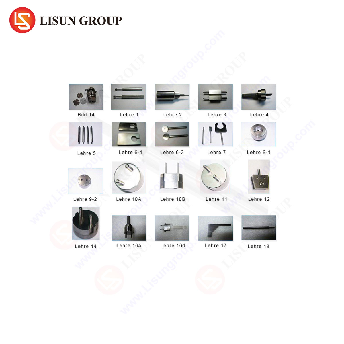
The LISUN Gauges for Plugs and Sockets series represents a specialized implementation of this technology. Designed to meet the exacting requirements of certification bodies (such as UL, TÜV, Intertek) and high-volume manufacturers, these gauges translate abstract standard clauses into a deterministic, operator-independent test process.
The operational principle of such a system involves a servo-driven or precision lead-screw mechanism that advances the test plug. Integrated micro-ohmmeters or dedicated semiconductor-based detection modules monitor each pin’s circuit. Upon detecting a closed circuit (typically at a threshold resistance below 10-50 Ohms), the system captures the high-resolution encoder count. Software then calculates and displays the individual contact points and the differential distances. Advanced models feature automated pass/fail judgment based on user-defined limits, data logging for traceability, and the ability to test multiple insertion cycles to verify consistency.
Key specifications for a robust FCP verification system, as embodied by the LISUN series, include:
- Displacement Resolution: ≤ 0.01 mm, ensuring measurement uncertainty is a fraction of the compliance threshold.
- Detection Circuit: Low-voltage (≤ 5V DC), current-limited (< 100 mA) sensing to prevent contact damage.
- Insertion Force Control: Programmable or mechanically limited insertion force to comply with standard stipulations (often 20-30 N).
- Fixture Versatility: Adaptors and fixtures for a comprehensive range of global plug patterns (Type A, B, C, D, E, F, G, I, etc.) and socket configurations, including those with protective shutters.
- Data Output: Direct generation of test reports compliant with ISO/IEC 17025 requirements for calibration and testing laboratories.
Implications for Product Design, Manufacturing, and Field Safety
The FCP distance is a direct output of design choices and manufacturing precision. For designers, it dictates the relative lengths of pins within a plug and the depth and spring geometry of contacts within a socket. A pin that is too short or a contact spring that is set too deep can instantly render a design non-compliant and unsafe.
In manufacturing quality control, FCP verification serves as a critical in-process or end-of-line test. Statistical process control (SPC) charts tracking FCP distance can reveal tooling wear in injection molds for plugs or drift in the assembly fixtures for socket contacts. A gradual reduction in measured FCP distance can predict future non-conformances before they result in a batch failure, enabling preventative maintenance.
For certification laboratories and safety inspectors, FCP testing is a non-negotiable type test. It provides objective, quantitative evidence that a product’s fundamental safety architecture functions as intended. Failure in this test is a critical fault, directly indicative of a potential electric shock hazard.
Comparative Advantages of Integrated Verification Systems
The alternative to a dedicated gauge—a custom-built jig using separate digital indicators, power supplies, and manually operated slides—is fraught with drawbacks. Such setups suffer from higher measurement uncertainty, operator dependency, poor repeatability, and a lack of audit trail. Integrated systems like the LISUN gauges offer distinct advantages:
- Standardization: They ensure every test, whether performed in Shanghai, Stuttgart, or Chicago, follows an identical protocol, aligning global supply chains.
- Efficiency: Automated testing reduces operator time per unit and eliminates subjective judgment calls.
- Traceability: Electronic data records provide immutable proof of compliance for quality audits and regulatory submissions.
- Preventative Diagnostics: Trend analysis of FCP data can diagnose upstream manufacturing issues unrelated to the socket itself, such as inconsistencies in plug pin alloy conductivity or plating quality, which affect the detection circuit’s response.
Conclusion
First Contact Point distance verification transcends simple dimensional inspection. It is a functional safety test that validates the critical “first-make, last-break” protective principle in electrical connectors. As safety standards evolve and the density of electrical devices in domestic and commercial environments increases, the rigor of this verification becomes ever more paramount. The deployment of precise, reliable, and standardized instrumentation is not merely a convenience for manufacturers and test labs; it is a necessary component in the global ecosystem of electrical safety, ensuring that a fundamental safeguard is consistently and accurately validated across billions of connections.
FAQ: First Contact Point Distance Verification
Q1: Can a plug that passes dimensional checks still fail an FCP distance test?
Yes, absolutely. Dimensional checks of pin lengths are static measurements. The FCP test is a dynamic functional test. A plug with pins of correct length could still fail if, for example, the socket’s earth contact spring has excessive resistance or is mechanically obstructed, delaying electrical continuity. The FCP test integrates the performance of both mating components.
Q2: How often should an FCP verification gauge be calibrated?
Calibration intervals should be based on risk, usage frequency, and adherence to quality standards like ISO 17025. For high-volume testing labs, an annual calibration of the displacement encoder and a verification of the electrical detection circuit’s sensitivity is typical. A routine daily or weekly check using a master reference plug/socket set is recommended to ensure ongoing performance.
Q3: Are FCP testers capable of validating shutter operation on socket-outlets?
While the primary function is contact sequence verification, many advanced FCP gauges, including certain LISUN models, offer optional or integrated shutter interlock testing. This involves using test pins of specific diameters to verify that shutters (safety barriers) only open when sufficient force is applied simultaneously to both shutter actuators, as per standards like IEC 60884-1 Clause 9.5.
Q4: What is the consequence of an FCP distance measuring exactly at the minimum limit (e.g., 1.0 mm)?
A measurement exactly at the minimum limit is technically compliant. However, from a quality and safety margin perspective, it is a cause for investigation. Given inherent measurement uncertainty and the potential for wear over the product’s service life, a result at the absolute limit suggests the design is operating with minimal safety margin. Robust manufacturing processes aim for results consistently centered well above the minimum threshold.
Q5: Can these systems test polarized plugs (where L and N pins are distinct)?
Yes. Competent FCP verification systems are configured with independent detection circuits for Line, Neutral, and Earth pins. For polarized systems (e.g., North American NEMA 5-15), the test verifies that the earth pin contacts first, and then typically that the neutral pin contacts before the line pin, providing an additional layer of safety sequencing. The software is configured with the expected sequence for the plug standard under test.