


Flame Test Analysis: Principles and Applications in Material Safety Compliance
The proliferation of complex electrical and electronic equipment across modern society necessitates rigorous evaluation of material behavior under fault conditions. Among the most critical assessments is the analysis of a material’s resistance to ignition and its ability to limit flame propagation. Flame test analysis, governed by a suite of international standards, provides a fundamental, empirical methodology for quantifying these properties. This technical examination delves into the underlying principles of standardized flame testing, with a specific focus on the needle-flame test methodology as exemplified by advanced instrumentation like the LISUN ZY-3 Needle Flame Test Apparatus. The discussion will encompass the scientific rationale, procedural execution, relevant standards, and cross-industry applications, providing a comprehensive resource for engineers, compliance officers, and product safety specialists.
The Thermodynamic and Chemical Basis of Ignition Resistance
At its core, flame test analysis is an applied study of a material’s response to a localized thermal insult. The process interrogates several interrelated physicochemical properties: thermal conductivity, specific heat capacity, pyrolysis kinetics, and flammability of evolved gases. When a calibrated flame is applied to a test specimen, energy is transferred via convection and radiation, raising the surface temperature. If the thermal energy input exceeds the sum of energy dissipated through conduction into the bulk material, convection to the surrounding air, and the endothermic energy required to pyrolyze the solid polymer into volatile fragments, the surface reaches its pyrolysis temperature.
Subsequent ignition occurs when the concentration of these pyrolyzates in the air mixture adjacent to the surface reaches the Lower Flammability Limit (LFL) and the temperature attains or exceeds the auto-ignition temperature of the gas mixture. A material’s performance in a flame test is therefore a composite function of its intrinsic thermal properties and the chemical structure of its polymer matrix. Additives such as halogenated compounds, metal hydroxides (e.g., aluminum trihydrate), phosphorus-based systems, and intumescent agents work by altering this energy balance—either through endothermic decomposition, dilution of flammable gases, or the formation of an insulating char layer.
The Needle Flame Test: Simulating Fault-Induced Ignition Sources
While many flame tests, such as the glow-wire or horizontal/vertical burn tests, utilize larger, more sustained flames, the needle-flame test addresses a distinct hazard scenario. It is designed to simulate the effect of small flames that may arise from faulty components—such as overheated resistors, poor solder joints, or arcing in low-current circuits—or from incidental exposure to small ignition sources like matches or candles. The test is characterized by its use of a small, defined flame with a nominal thermal power output.
The governing principle involves applying a specified needle flame from a butane-fed burner to the test specimen for a predetermined period (typically 30 ± 1 seconds). The key observational parameters post-application are:
- Duration of Flaming Combustion: The time the specimen continues to flame after removal of the test flame.
- Duration of Glowing Combustion: The time the specimen continues to glow post-flame.
- Extent of Flame Spread: Measured from the point of application.
- Behavior of Dripping Particles: Whether they ignite a surgical cotton indicator placed below the specimen.
The pass/fail criteria, detailed in standards like IEC 60695-11-5, are stringent. Generally, the test is failed if flaming or glowing persists beyond 30 seconds after flame removal, if flame spread exceeds specified limits, or if ignited droplets compromise the indicator. This makes the test particularly challenging for unfilled thermoplastics and certain thin-walled components.
Instrumentation and Precision: The LISUN ZY-3 Needle Flame Test Apparatus
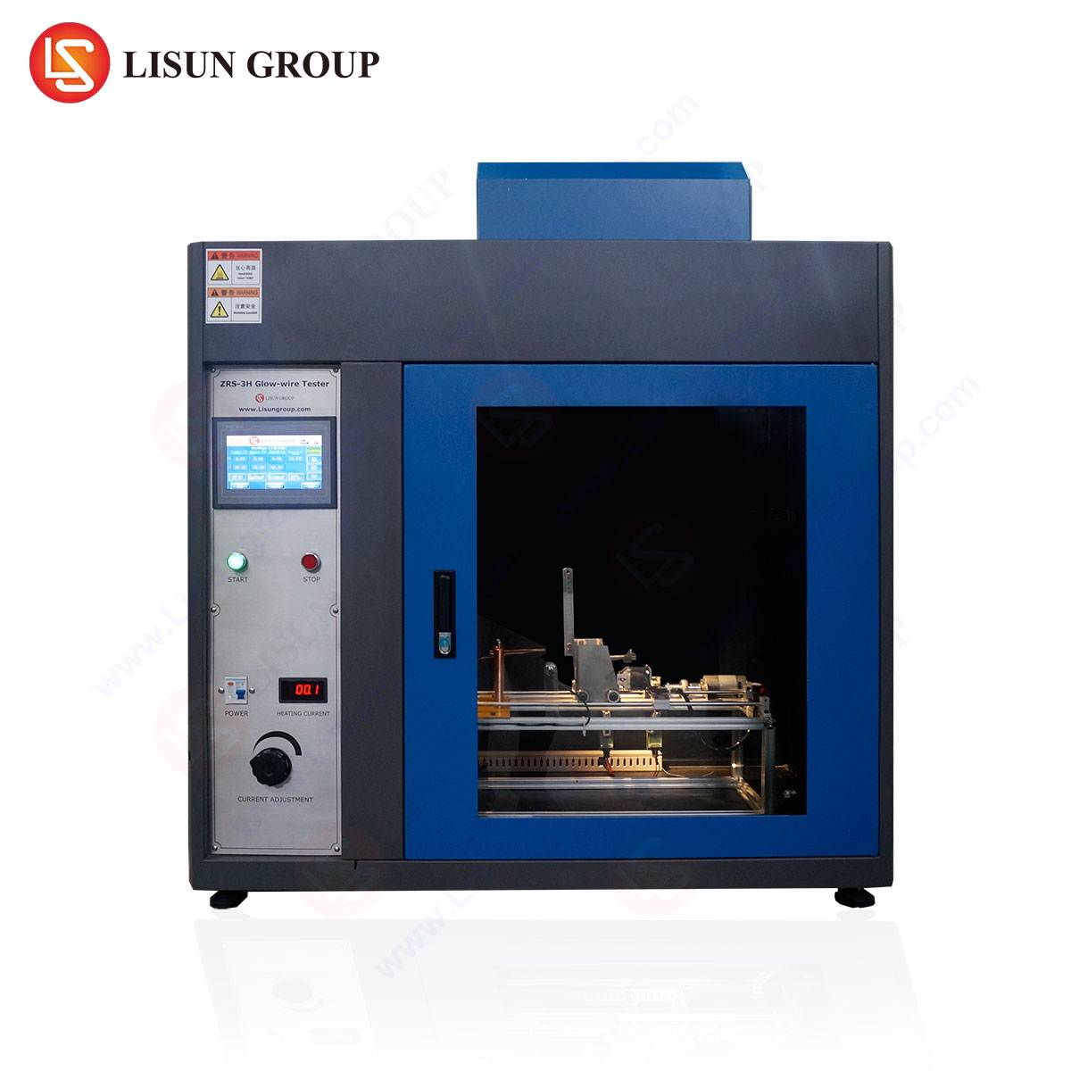
Accurate and reproducible flame testing demands instrumentation that provides exceptional control over all test variables. The LISUN ZY-3 Needle Flame Test Apparatus is engineered to meet the exacting requirements of IEC 60695-11-5, GB/T 5169.5, and related standards. Its design philosophy centers on eliminating operator variance and ensuring consistent thermal insult, which is paramount for reliable comparative analysis between material formulations or product designs.
Key Technical Specifications and Operational Principles:
- Flame Calibration System: The apparatus features an integrated flame calibration rig. The critical parameter is the flame temperature, verified using a 0.5mm diameter Type K (NiCr-NiAl) thermocouple. The system must achieve a temperature rise of 1000 ± 20°C within 23.5 ± 1.0 seconds when the thermocouple is positioned in the flame core. The ZY-3’s precision gas flow control and burner design ensure consistent repeatability of this thermal output.
- Programmable Test Automation: Testing sequences—including flame application duration, post-application observation timing, and retraction mechanisms—are managed via a programmable logic controller (PLC) with an intuitive HMI interface. This automation removes manual timing errors and ensures strict adherence to the standard’s temporal requirements.
- Specimen Positioning and Fixturing: The unit includes a fully adjustable specimen holder capable of positioning test items in various orientations (vertical, horizontal, or at defined angles) as required by the end-product standard. A calibrated scale is integrated for precise measurement of flame spread.
- Safety and Containment: A sealed test chamber with a transparent, high-temperature observation window contains the test. An integrated exhaust system safely removes combustion products, maintaining laboratory air quality. Automatic gas shut-off valves enhance operational safety.
- Data Logging: While primarily a pass/fail test, precise documentation of combustion times is essential. The system can log and store test parameters and results for traceability and quality audit purposes.
Competitive Advantages in Compliance Testing:
The ZY-3’s primary advantage lies in its standardization and reliability. By automating the most critical and variable steps—flame consistency and timing—it generates data that is defensible in regulatory submissions. Its compliance with both international (IEC) and national (GB/T) standards makes it a versatile tool for global markets. Furthermore, its robust construction and safety features minimize downtime and operational risk, providing a lower total cost of ownership for high-throughput compliance laboratories.
Cross-Industry Application Scenarios and Test Rationale
The needle-flame test is specified in numerous end-product safety standards across diverse sectors. Its application is crucial wherever a small, localized fault could lead to a fire hazard.
- Electrical and Electronic Equipment & Industrial Control Systems: For printed circuit board (PCB) substrates, relay housings, terminal blocks, and wire harness channels within control cabinets. The test evaluates whether a fault on a single component, like a failing semiconductor, can ignite its mounting substrate or surrounding enclosures.
- Household Appliances and Consumer Electronics: Applied to internal shrouds, switch housings, connector bodies, and remote control casings. It assesses the risk from an internal electrical fault or from external exposure to a small candle flame in a domestic setting.
- Automotive Electronics: Used for testing non-metallic materials in electronic control units (ECUs), sensor housings, wiring ducting, and infotainment system components. It simulates potential faults in the 12V/24V electrical system that could generate small arcs or overheated connections.
- Lighting Fixtures: Particularly for LED driver housings, diffuser materials, and plastic components in proximity to the light source. It evaluates resistance to ignition from a failing driver component or from thermal stress.
- Telecommunications Equipment: For testing chassis materials, fan housings, and cable management guides in routers, switches, and base station electronics. The goal is to ensure a fault in one card or power supply does not propagate.
- Medical Devices and Aerospace Components: Applied to non-metallic parts in monitoring equipment, handheld diagnostic devices, and aircraft cabin entertainment systems. The extreme emphasis on safety and reliability in these fields mandates validation against even small ignition sources.
- Electrical Components and Cable Systems: For switches, socket faces, circuit breaker housings, and the sheathing of wiring harnesses. The test checks material response to overheating at connection points.
- Office Equipment: For internal plastics in printers, power supplies, and external casings that may be near potential ignition sources in an office environment.
Standards Framework and Comparative Test Methodologies
Flame test selection follows a hierarchical standards framework. Generic requirement standards (e.g., IEC 62368-1 for audio/video and IT equipment) cite basic safety standards (e.g., the IEC 60695-11 series) which define the test methods. The needle-flame test, defined in IEC 60695-11-5, is often employed when the hazard analysis identifies a “small flame” risk.
It is instructive to contrast it with other common tests:
- Glow-Wire Test (IEC 60695-2-11): Simulates overheating from resistive components. It uses a heated element rather than an open flame, assessing ignition and self-extinguishing properties.
- Horizontal/Vertical Flame Test (UL 94): A simpler, more traditional test primarily for material qualification, using a larger Bunsen burner flame. It classifies materials (e.g., V-0, V-1, V-2, HB) based on burn rate and dripping behavior.
- Needle-Flame Test: Uniquely focuses on the propagation risk from a small flame. A material may achieve a V-0 rating in UL 94 yet still fail a needle-flame test if it sustains burning locally for an extended period, highlighting the test’s specific and complementary role.
Table 1: Key Comparative Parameters of Common Ignition Tests
| Test Method (Standard) | Ignition Source Simulated | Typical Application | Primary Measurement |
| :— | :— | :— | :— |
| Needle-Flame (IEC 60695-11-5) | Small flames from faults (e.g., arcs, matches) | End-product safety, small components | Flame persistence, spread, droplet ignition |
| Glow-Wire (IEC 60695-2-11) | Overheated or glowing elements | Electrically energized parts, fault conditions | Ignition temperature, flame duration |
| Vertical Burn (UL 94) | General flammability exposure | Material pre-qualification, comparative ranking | After-flame time, dripping, burn length |
Interpretation of Results and Material Development Implications
A failed needle-flame test necessitates a root-cause analysis and material or design remediation. Engineers must determine if failure was due to the base polymer’s inherent flammability, insufficient wall thickness (affecting heat sink capacity), part geometry that fosters flame holding, or the absence of effective flame retardants.
Subsequent mitigation strategies may include:
- Material Reformulation: Incorporating synergistic flame-retardant packages. For instance, a polyamide (PA) housing might be compounded with red phosphorus and a nitrogen compound to promote char formation.
- Design Modifications: Adding thermal barriers, ribs to act as flame stops, or increasing the distance (creepage and clearance) between potential ignition sources and plastic parts.
- Component Shielding: Placing a metal heatsink or shield between a high-risk component (e.g., a varistor) and the plastic enclosure.
- Alternative Material Selection: Switching from a generic ABS to a more inherently resistant polymer like polyphenylene sulfide (PPS) or a flame-retardant grade of polycarbonate (PC).
The data generated by precise apparatus like the LISUN ZY-3 is instrumental in this iterative development process, allowing for quantitative comparison between different prototypes and formulations.
Conclusion
Flame test analysis, particularly the needle-flame methodology, remains an indispensable component of product safety engineering. It provides a empirically validated means of assessing a critical risk scenario that theoretical analysis alone cannot fully capture. The integrity of this assessment is wholly dependent on the precision, repeatability, and standardization of the test equipment employed. As regulatory landscapes evolve and materials become more complex, the role of sophisticated, automated test apparatus in ensuring compliance, guiding design, and ultimately safeguarding lives and property will only increase in significance. The principles outlined herein form the foundation for understanding this vital field of applied materials science.
FAQ: Needle Flame Testing and the LISUN ZY-3 Apparatus
Q1: What is the primary difference between the needle-flame test and the more common UL 94 test?
The UL 94 test is primarily a material screening tool that uses a larger Bunsen burner flame to rank the general flammability of plastics (e.g., V-0, HB). The needle-flame test is an end-product test that simulates a specific, small-scale fault condition. It assesses whether a localized flame on a finished product or sub-assembly will cause sustained burning or flame spread. A material with a good UL 94 rating can still fail a needle-flame test if it cannot self-extinguish when subjected to a small, persistent flame.
Q2: How often does the LISUN ZY-3 apparatus require calibration, and what is involved?
For compliance with laboratory quality standards (e.g., ISO/IEC 17025), a full calibration should be performed annually or as per the laboratory’s controlled procedure. Critical calibration checks include verifying the temperature rise of the reference thermocouple (1000°C in 23.5s), confirming the accuracy of the application timer, and ensuring the gas flow rate is set to produce the correct flame height (12mm ± 1mm). The ZY-3 is designed to facilitate these checks with integrated fixtures and clear procedures.
Q3: Can the ZY-3 test specimens that are not flat plates, such as irregularly shaped components or complete small assemblies?
Yes. A key feature of the ZY-3 is its versatile and adjustable specimen holder. It can securely fixture three-dimensional components, enclosures, or mock-ups of end products in the orientation specified by the applicable standard. The test flame can be applied to specific, pre-determined points of vulnerability on the assembly, such as seams, vents, or areas adjacent to internal heat sources.
Q4: Which industries or product standards most frequently mandate the needle-flame test?
The test is widely referenced in safety standards for IT/AV equipment (IEC 62368-1), household appliances (IEC 60335-1), measurement and control equipment (IEC 61010-1), and medical electrical equipment (IEC 60601-1). It is also commonly found in automotive (various ISO and SAE standards), telecommunications, and lighting product specifications where a risk assessment identifies a potential small-flame hazard.
Q5: What are the critical safety features of the ZY-3 for laboratory operation?
The apparatus incorporates multiple safety systems: a fully enclosed stainless steel test chamber to contain flames and particles, a forced exhaust to remove toxic combustion gases, an automatic gas shut-off valve that activates upon test completion or in case of a system fault, and a flame-retardant viewing window. These features protect the operator and prevent secondary ignition events in the laboratory environment.