


The Metrological Imperative: Advanced Gauge Systems for Verifying Plug and Socket Integrity
The global infrastructure for electrical connectivity relies fundamentally on the humble plug and socket interface. This critical junction is the primary point of electrical energy transfer for countless devices and systems, from domestic appliances to industrial machinery. The safety, reliability, and longevity of this interface are not matters of chance but of rigorous design and precise manufacturing. Central to this process is the deployment of specialized metrological equipment designed to validate the physical and safety-critical dimensions of plugs, sockets, caps, and covers. This article examines the technical principles, application, and critical importance of gauge systems, with a specific focus on the LISUN Gauges for Plugs and Sockets, in ensuring compliance with international safety standards.
Fundamental Principles of Dimensional Verification in Electrical Components
The primary function of a gauge in this context is to provide a pass/fail assessment of key dimensional attributes that are directly linked to safety performance. Unlike a variable measuring instrument that provides a quantitative value, a gauge is a fixed-limit instrument. Its design is predicated on the “Taylor Principle,” which dictates that a gauge must assess both the size and the geometric form of a feature to ensure it lies within the prescribed tolerance zone. For electrical connectors, this involves verifying that a plug will mate with a socket with sufficient mechanical security to prevent accidental disconnection, yet without excessive force that could damage the contacts or pose a user hazard. Simultaneously, it must ensure that access to live parts is prevented under all normal and single-fault conditions. The gauges are physical manifestations of the worst-case allowable dimensions as defined by standards such as IEC 60884-1 for plugs and socket-outlets.
These assessments are bifurcated into two main categories: “GO” gauges and “NO-GO” gauges. A GO gauge must fully enter or mate with the component under test without undue force, confirming that the minimum material condition is not violated—for instance, that a plug is not too small. Conversely, a NO-GO gauge must not enter or mate under a specified force, confirming that the maximum material condition is not exceeded—for instance, that the apertures in a socket-outlet are not too large, which could allow access to live pins or the insertion of an incompatible, hazardous plug. The application of specified test forces, as per standard protocols, is crucial to eliminating subjective operator judgment and ensuring repeatable, reliable results.
Anatomizing the LISUN Gauges for Plugs and Sockets System
The LISUN Gauges for Plugs and Sockets represent a comprehensive, standards-compliant metrology system engineered for quality control laboratories, certification bodies, and manufacturing facilities. The system is not a single tool but a coordinated set of individual gauges, each designed to verify a specific safety-critical parameter. The construction of these gauges typically involves hardened and stabilized tool steel or other wear-resistant materials to ensure long-term dimensional stability and mitigate the effects of repeated use on measurement accuracy. The surface finish is critically controlled to prevent false positives from friction or material adhesion.
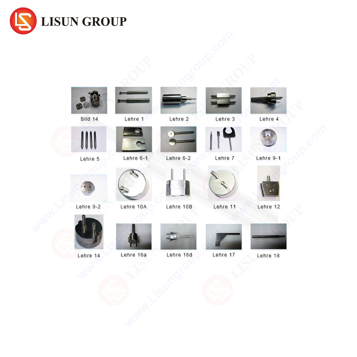
The system is modular, addressing the myriad requirements of international standards for various plug and socket types (e.g., Type A, B, C, D, E, F, G, I, etc.). A typical LISUN kit includes, but is not limited to, the following gauge types:
- Pin Gauge Set: These are precision-ground cylindrical pins used to verify the internal diameters of socket contact tubes. A GO pin of maximum allowable pin diameter must enter the contact tube, while a NO-GO pin of the minimum allowable pin diameter plus a tolerance must not enter. This ensures proper electrical contact and mechanical grip on the plug pins.
- Plug Gauge (Check Pin): This is a full-scale model of a plug, constructed to the maximum allowable dimensions permitted by the standard. It is used to verify that a socket-outlet can accept a worst-case sized plug without damage and that the shutters, if present, function correctly.
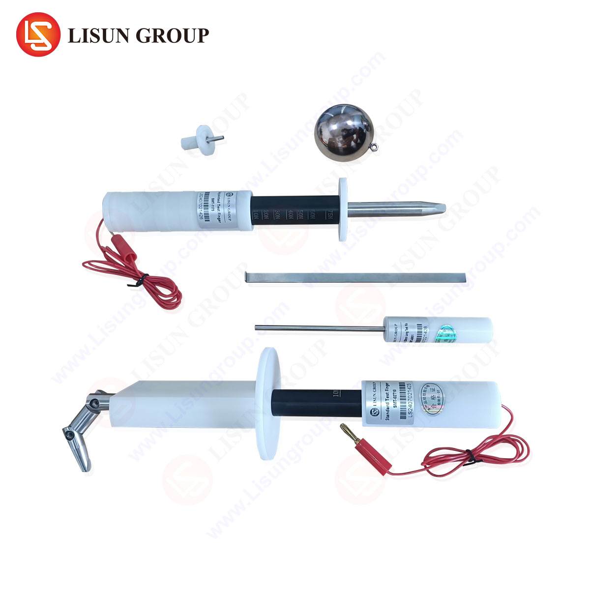
- Access Probe Gauges (Standard Test Finger): Perhaps the most critical safety gauge, this device simulates a human finger or a foreign object. Defined in standards like IEC 61032, the test finger is applied to the socket-outlet with a specified force. It must not contact live parts, demonstrating that the protective shutters or the geometry of the socket apertures provide adequate protection against electric shock.
- Impact Test Gauges: These are hemispherical or specified geometry probes used to verify the mechanical strength of covers and enclosures. They are dropped from a defined height onto the component to ensure it can withstand incidental impact without exposing live parts or failing in a hazardous manner.
- Socket Entry Gauge: This gauge verifies the size and shape of the socket entry. It ensures that a plug can be inserted correctly and that the geometry prevents the insertion of pins into the wrong apertures, a key feature for polarized and earth-pin-dependent designs.
Quantifying Performance: Specifications and Tolerances
The efficacy of a gauge system is defined by its adherence to the dimensional and force tolerances stipulated in international standards. The LISUN gauges are manufactured with precision that far exceeds the tolerances required for the components they test, ensuring the measurement uncertainty of the gauge itself is a negligible contributor to the overall test process.
Table 1: Exemplary Specifications for a LISUN Pin Gauge Set (IEC 60884-1)
| Gauge Type | Nominal Dimension | Tolerance on Gauge | Application Force | Standard Compliance |
|---|---|---|---|---|
| GO Pin | 4.8 mm (Max Pin Dia.) | ± 0.002 mm | 30 N ± 3 N | IEC 60884-1, Clause 9 |
| NO-GO Pin | 4.3 mm (Min Pin Dia. + Tol.) | ± 0.002 mm | 30 N ± 3 N | IEC 60884-1, Clause 9 |
| Test Probe | Simulated Object | Application Force / Moment | Pass/Fail Criteria | Standard Compliance |
| Standard Test Finger | Jointed Finger | 10 N ± 1 N | No contact with live parts | IEC 61032, Fig. 2 |
| Impact Test Gauge | 5kg Hemispherical | Dropped from 100mm | No unacceptable damage | IEC 60884-1, Clause 24 |
The materials used, such as high-carbon chromium steel with a surface hardness of HRC 60-65, ensure that the gauges resist deformation and wear over thousands of cycles, maintaining calibration integrity. Each gauge is typically supplied with a calibration certificate from an accredited laboratory, tracing its dimensions back to national measurement standards.
Application in the Product Lifecycle: From R&D to Quality Audit
The deployment of these gauge systems spans the entire product lifecycle. During the Research and Development phase, engineers use the gauges to validate prototype designs and tooling before mass production. This early-stage verification prevents costly design flaws and ensures the product will pass formal certification.
In the Manufacturing and Production phase, the gauges are indispensable tools on the factory floor. They are used for first-article inspection, in-process checks, and final random quality audits. The simplicity of the GO/NO-GO methodology allows for rapid testing by production line operators, providing immediate feedback and enabling real-time process control. For instance, a trend of failing GO pin tests on socket contact tubes may indicate tool wear in the stamping or forming machinery, allowing for preventative maintenance before non-conforming products are manufactured.
For Third-Party Certification Bodies and Testing Laboratories, such as those providing UL, CSA, TÜV, or Intertek certification, the LISUN gauge system is a mandatory part of the test equipment inventory. Its use is non-negotiable for demonstrating compliance with the mandatory safety tests required for market access. The robustness and traceable calibration of these gauges are paramount for the integrity of the certification process.
Comparative Advantages in a Precision-Driven Market
The market for test equipment is competitive, yet certain design philosophies distinguish high-performance gauge systems. The LISUN system is characterized by several key advantages rooted in its engineering.
First is the Metrological Integrity. The use of hardened, stabilized materials and precision grinding and lapping processes results in gauges with exceptional dimensional stability and surface finish. This reduces measurement uncertainty and prevents false failures caused by gauge wear or surface roughness.
Second is Comprehensive Standards Coverage. The system is designed as a modular toolkit, with configurations available for nearly all international plug and socket standards. This eliminates the need for laboratories to source gauges from multiple suppliers, ensuring consistency and simplifying procurement and calibration management.
Third is Ergonomic and Functional Design. While a gauge is a functional tool, attention to detail in handle design, weight distribution, and clear, permanent marking reduces operator fatigue and minimizes the risk of misapplication. The gauges are often anodized or marked with color-coding for quick identification, a critical feature in a high-throughput testing environment.
Finally, the Full-System Traceability provided with calibration certificates for each gauge is not merely a value-added feature but a fundamental requirement for any accredited testing facility. This end-to-end traceability underpins the entire chain of trust in the product certification process.
Ensuring Long-Term Metrological Integrity: Calibration and Maintenance
The precision of any gauge system degrades over time due to normal wear and environmental factors. A rigorous calibration schedule is therefore essential. It is recommended that gauge sets are calibrated at least annually, or more frequently based on usage volume, in accordance with ISO/IEC 17025 requirements for testing laboratories. The calibration process involves using coordinate measuring machines (CMMs) and optical comparators to verify every critical dimension of the gauge against its design specification. Any gauge found to be outside its tolerance must be taken out of service and either re-worked or replaced. Proper storage in controlled environments and in protective cases is also critical to prevent corrosion, physical damage, and dust accumulation that could affect performance.
Frequently Asked Questions (FAQ)
Q1: How frequently should LISUN Gauges be calibrated to maintain accuracy?
A1: The calibration interval depends on usage frequency and the quality control procedures of the facility. For most high-volume testing environments, an annual calibration cycle is the minimum recommendation. Laboratories operating under ISO/IEC 17025 accreditation must define and justify their calibration intervals based on a risk assessment and historical performance data of the equipment. A gauge that shows signs of wear or damage should be calibrated immediately, regardless of the scheduled interval.
Q2: Can one set of LISUN Gauges be used to test multiple international plug types?
A2: No, a single gauge is typically designed for a specific plug/socket standard (e.g., Type G (UK) or Type B (North American)). The LISUN system is modular, meaning a laboratory would procure a dedicated gauge set for each plug type they need to certify. This is because the dimensional and geometric requirements, including pin spacing, diameter, and length, are distinctly defined for each standard.
Q3: What is the consequence of a socket failing the “Standard Test Finger” probe test?
A3: Failure of this test is a critical safety non-conformance. It indicates that the protective shutters within the socket have not functioned correctly, or the aperture geometry is incorrect, allowing simulated access to live electrical contacts. A product failing this test poses a severe risk of electric shock and would immediately fail certification. The design must be revised to improve the shutter mechanism or the internal barrier geometry.
Q4: In a production setting, if a component fails a NO-GO gauge test, what is the typical corrective action?
A4: A NO-GO gauge failure indicates the component is too large or an aperture is too big. The immediate action is to quarantine the non-conforming batch. The root cause must then be investigated, which often points to tooling wear in the molding, stamping, or machining process. For example, a worn mold cavity for a socket face may produce apertures that are oversize. Corrective action involves repairing or replacing the worn tooling and re-verifying the process with the gauges before resuming production.