


The Critical Role of Shutter Force Gauges in Ensuring Electrical Outlet Safety
Electrical safety in residential, commercial, and industrial environments hinges upon the integrity of countless components, with the humble power outlet serving as a primary interface between users and the electrical grid. A critical safety feature within modern socket-outlets, particularly those rated for 2.5 A and above in many international standards, is the protective shutter mechanism. These shutters are designed to prevent the insertion of foreign objects, thereby mitigating the risk of electric shock. The efficacy of this safety system, however, is directly contingent upon the force required to open it. Excessive force can damage the shutter mechanism or deter legitimate use, while insufficient force compromises the fundamental safety objective. Consequently, the precise measurement of this actuation force is not merely a quality control step but a fundamental requirement for compliance with stringent international safety standards. This article delineates the engineering principles, standardized testing methodologies, and instrumental requirements for the accurate quantification of shutter actuation force in 2.5 A outlets.
Fundamental Principles of Shutter Mechanism Operation and Safety
Shutter mechanisms in socket-outlets are sophisticated mechanical assemblies engineered to permit access only upon the simultaneous insertion of both plug pins. This design philosophy is rooted in the principle of selective access, preventing children or untrained individuals from making contact with live parts using single, conductive objects such as keys or hairpins. The shutters are typically spring-loaded and interlocked, requiring a specific, calibrated force to overcome the spring tension and frictional forces within the assembly. The operational lifetime of the outlet is intrinsically linked to the durability of this mechanism; each actuation cycle contributes to mechanical wear. The initial force required to open the shutters must therefore be optimized to balance safety with usability over the product’s entire service life. This balance is precisely defined in various national and international standards, including IEC 60884-1, which stipulates explicit force limits and testing protocols for shutter assemblies. The mechanical design must account for material properties, spring constants, and geometric tolerances, all of which converge to define the actuation force characteristic that requires precise measurement.
Quantifying Usability and Safety Through Actuation Force Measurement
The measurement of shutter actuation force provides a quantifiable metric for two paramount, and often competing, design criteria: safety and usability. From a safety perspective, the force must be sufficiently high to deter accidental or intentional operation by young children. Empirical studies and standards committees have established minimum force thresholds that are deemed effective for this purpose. Conversely, from a usability standpoint, the force cannot be so high as to make the insertion of a compliant plug difficult for an average adult, including those with reduced hand strength or dexterity. Excessive insertion force can lead to user frustration, potential damage to the plug or socket contacts, and in extreme cases, a safety hazard if a user employs excessive leverage that damages the installation. Therefore, the target force window is narrow and critically defined. Precise measurement ensures that manufactured outlets consistently fall within this specified range, validating the design and manufacturing process. It is a direct measure of product performance and compliance, serving as a key performance indicator (KPI) in quality assurance laboratories and production lines.
Introduction to the LISUN Gauge for Plugs and Sockets
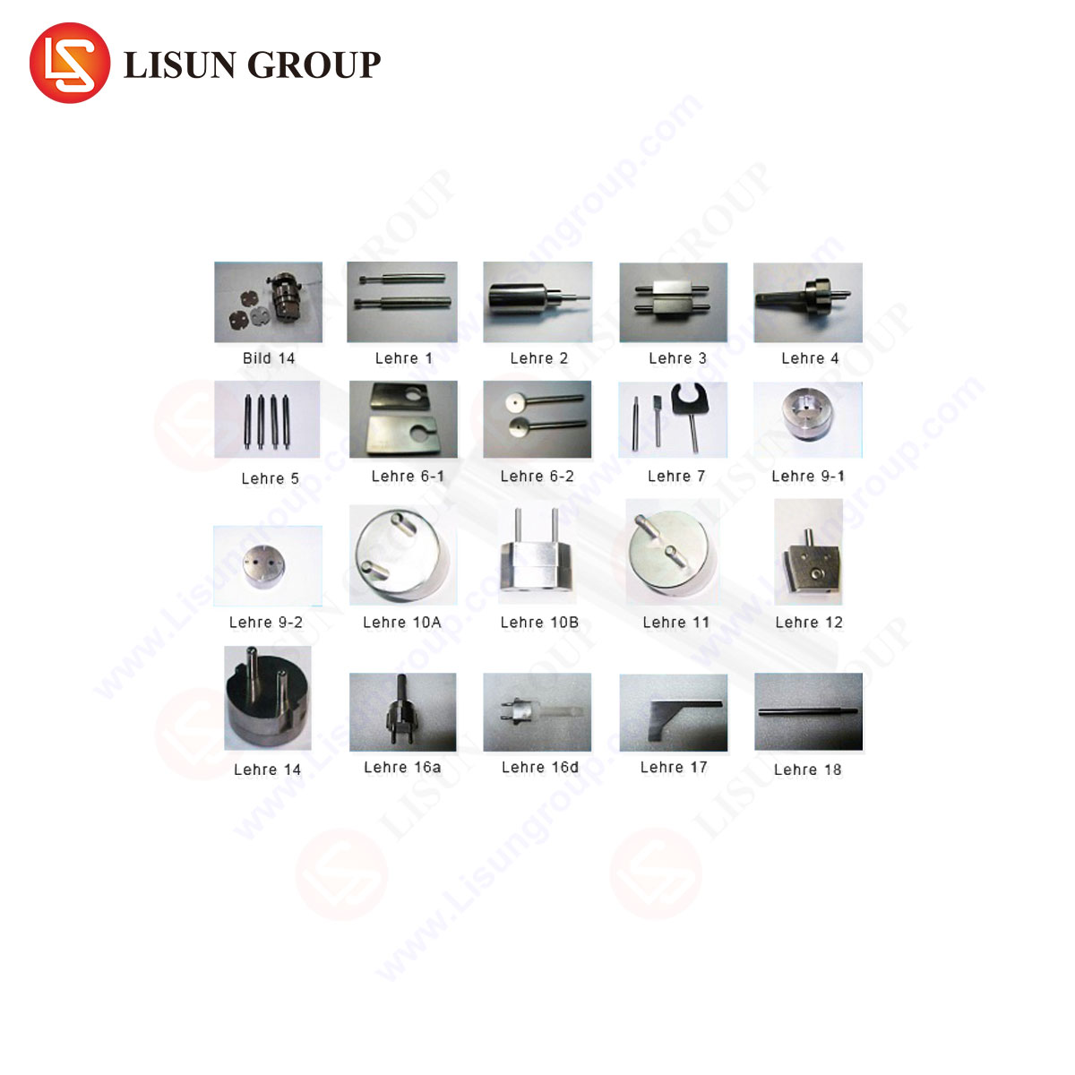
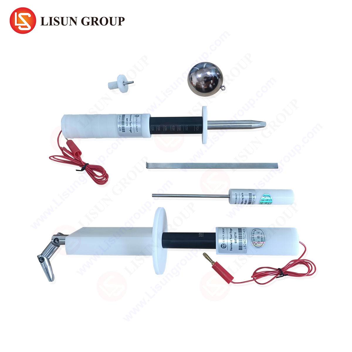
To address the stringent requirements for shutter force testing, specialized instrumentation is required. The LISUN Gauge for Plugs and Sockets represents a category of precision test equipment engineered specifically for this application. These gauges are not simple force probes; they are integrated systems designed to simulate the action of a standard plug while providing accurate, repeatable, and traceable force and travel distance measurements. The fundamental design of a LISUN gauge typically incorporates a high-accuracy force transducer, a precision linear actuator for controlled movement, a displacement encoder, and a dedicated microcontroller for data acquisition and processing. The system is calibrated against national standards, ensuring that the force measurements are metrologically sound. For testing 2.5 A outlets, the gauge is configured with test pins that precisely mimic the dimensions, spacing, and tip geometry of a standard 2.5 A plug, as specified in the relevant standard (e.g., the BS 1363 pin configuration for UK-style plugs). This attention to detail is crucial, as the geometry of the pin tip can significantly influence the point of contact and the resulting force required to cam the shutter open.
Technical Specifications of a Modern Shutter Force Gauge
A contemporary LISUN gauge is characterized by a set of robust technical specifications that enable it to perform its duty with the required precision. The force measurement range is typically selectable, with a common range for outlet testing being 0 to 50 Newtons, with a resolution of 0.1 N or better. The accuracy of the force sensor is paramount, often specified at ±0.5% of full scale or ±1% of reading. Equally important is the travel displacement measurement, which must have a resolution of at least 0.1 mm to accurately plot the force-distance curve during the pin insertion cycle. The gauge’s drive mechanism must provide a constant, programmable test speed, usually within a range of 1 to 500 mm/min, allowing for simulation of both slow, deliberate insertion and a more rapid, user-representative action. Data output is typically presented via an integrated digital display and can often be exported via USB or RS-232 interfaces for further analysis and record-keeping. The following table summarizes typical core specifications for a gauge suitable for 2.5 A outlet testing:
| Parameter | Specification | Relevance |
|---|---|---|
| Force Range | 0 – 50 N | Covers the expected force spectrum for shutter actuation with ample margin. |
| Force Resolution | 0.1 N | Allows for detection of subtle force variations indicative of mechanism quality. |
| Force Accuracy | ±1% of reading | Ensures measurements are reliable and traceable for compliance reporting. |
| Travel Resolution | 0.1 mm | Precisely tracks pin movement relative to the shutter engagement point. |
| Test Speed | 1 – 500 mm/min (programmable) | Enables testing under different conditions as mandated by standards. |
| Data Interface | Digital Display, USB | Facilitates real-time monitoring and data logging for quality records. |
Standardized Testing Protocol for 2.5 A Outlet Shutters
The testing procedure using a LISUN gauge is a methodical process designed to eliminate operator influence and ensure repeatability. The outlet under test is securely mounted in a fixture to prevent movement. The gauge, equipped with the correct 2.5 A test pins, is aligned such that the pins will enter the socket apertures perpendicularly and simultaneously. The test is initiated, and the actuator drives the pins forward at a prescribed speed. As the pins contact the shutters, the force begins to increase. The gauge records the entire force profile throughout the travel distance. The key metric is the peak force encountered before the shutters fully open and the pins can travel freely. This peak force is the “force required to open the shutter.” The test is repeated multiple times (as per the standard, often 10 or more cycles) on the same outlet to ensure consistency and to check for rapid wear-in or failure of the mechanism. Some standards may also require testing at different pin insertion angles to simulate misuse. The LISUN gauge automates this entire sequence, calculating and displaying the peak force for each cycle, as well as statistical data such as the average and standard deviation, providing a comprehensive assessment of the shutter’s performance.
Interpreting Force-Displacement Curves for Mechanism Diagnostics
The raw data from a shutter force test is more than just a single peak force value; it is a force-displacement curve that offers a detailed diagnostic window into the mechanical health of the shutter assembly. A typical curve for a well-functioning shutter will show a gradual, smooth increase in force as the pins begin to cam against the shutter faces, culminating in a sharp peak at the moment the shutters snap open, followed by an immediate drop to a lower frictional force as the pins travel through the open apertures. Deviations from this ideal profile are highly informative. A curve with multiple, jagged peaks may indicate rough surfaces, burrs, or inconsistent lubrication on the shutter camming surfaces. A broader, flatter peak suggests excessive friction or an over-sprung mechanism. A significant leftward or rightward shift in the peak’s location on the displacement axis can point to issues with manufacturing tolerances or assembly alignment. By analyzing these curves, engineers can move beyond simple pass/fail criteria and perform root-cause analysis on production issues, leading to continuous improvement in design and manufacturing.
Compliance with International Standards: IEC 60884-1 and Beyond
The development, calibration, and use of shutter force gauges are intrinsically linked to international safety standards. IEC 60884-1, “Plugs and socket-outlets for household and similar purposes – Part 1: General requirements,” is a foundational document that specifies the safety requirements for these devices globally. It explicitly addresses shutter mechanisms, mandating that they shall only open when a force is applied simultaneously to both shutters. Furthermore, it stipulates that the force required to open the shutters shall not exceed a specified value, such as 40 Newtons for some socket types, when tested with a standardized gauge. National standards, such as BS 1363 in the United Kingdom or NF C 61-314 in France, often incorporate and expand upon these requirements with region-specific details. A LISUN gauge, when configured and calibrated appropriately, provides the objective evidence required to demonstrate conformity with these standards. This is critical for manufacturers seeking certification marks like the CE mark, UL listing, or the BSI Kitemark, as notified bodies and test laboratories rely on this data during type testing and surveillance audits.
Applications in Manufacturing Quality Assurance and Incoming Inspection
The primary application of the LISUN Gauge for Plugs and Sockets is within the manufacturing quality assurance (QA) workflow. Here, it serves as a critical tool for statistical process control (SPC). By testing a representative sample of outlets from each production batch, QA engineers can monitor the stability of the shutter actuation force. Any drift in the average force or an increase in variation can signal a problem in the injection molding process, a change in spring supplier, or wear on assembly tooling, allowing for corrective action before non-conforming products are produced in volume. Furthermore, these gauges are equally vital for component suppliers and for incoming inspection at the final assembly plant. A manufacturer of complete socket-outlets can use the gauge to validate the shutter sub-assemblies received from a specialist supplier, ensuring that only components meeting the precise force specifications enter the production line. This layered approach to quality control, from component-level verification to finished goods audit, is essential for maintaining brand reputation and ensuring end-user safety.
Comparative Advantages of Automated Gauge Systems Over Manual Methods
Prior to the widespread adoption of dedicated digital gauges, force testing was often performed using simple push-pull force gauges and fixtures, a method heavily reliant on operator technique and subject to significant human error. The LISUN gauge system offers several distinct competitive advantages. First is the elimination of operator influence; the automated, constant-speed insertion ensures that the test is performed identically every time, guaranteeing repeatability and reproducibility. Second, the digital data acquisition provides an objective, unalterable record of the test, which is invaluable for audit trails and compliance documentation. Third, the ability to capture the full force-displacement curve, as previously discussed, provides a level of diagnostic capability absent from manual methods that typically only record a peak value. Finally, the integration of such gauges into a factory’s data network enables real-time SPC and the creation of a comprehensive digital quality history for every product batch, facilitating traceability and advanced analytics.
Ensuring Long-Term Gauge Accuracy Through Metrological Traceability
The accuracy of a shutter force gauge is not a static property; it is maintained through a rigorous regimen of calibration. Metrological traceability, the unbroken chain of calibrations linking the gauge’s measurements to national or international standards, is a cornerstone of credible testing. LISUN gauges are designed to be calibrated using certified dead weights or a reference-grade force calibration system. The calibration interval is typically annual, though it may be more frequent in high-usage environments. A formal calibration certificate, issued by an accredited laboratory, documents the gauge’s performance across its measurement range, including any corrections or uncertainties. This process ensures that a force measurement of, for instance, 25 N made by a gauge in a factory in Asia is equivalent to the same measurement made by a certification body in Europe, creating a universal language of compliance and safety.
Frequently Asked Questions (FAQ)
Q1: Why is the test speed programmable on the LISUN gauge, and what speed should be used for testing 2.5 A outlets?
The test speed is programmable to allow compliance with various international standards, which may specify different insertion rates. A slower speed might be used for a highly precise measurement of the peak force, while a faster speed can better simulate a real-world user action. The specific speed for testing a 2.5 A outlet is dictated by the applicable standard. For example, a common specified speed is between 100 and 200 mm/min. The test protocol for the target market must always be consulted to select the correct speed.
Q2: Can a single LISUN gauge be used to test different types of outlets, such as those for 2.5 A, 13 A, or Schuko configurations?
Yes, most LISUN gauge systems are modular. The core force measurement unit remains the same, but the test pin assembly is interchangeable. To test a different socket type, the operator would simply attach the corresponding test pin fixture, which is manufactured to the precise dimensions and spacing required by that plug standard. The gauge’s software may also have pre-configured test programs for different outlet types.
Q3: What is the consequence of a shutter force measurement that is consistently below the minimum specified in the standard?
A force measurement below the minimum threshold indicates that the shutter mechanism is too easy to open. This constitutes a critical safety failure, as it suggests that the shutter could be operated by a single pointed object, bypassing the protective feature and creating a risk of electric shock. Production of outlets with such a characteristic must be halted immediately, and the root cause—likely an under-sprung mechanism, excessive wear, or a fundamental design flaw—must be identified and rectified.
Q4: How does the gauge account for the initial “free travel” before the pins contact the shutters?
Advanced LISUN gauges utilize a “trigger force” or “pre-travel” function. The system begins recording force and displacement from the start of the test cycle. The operator can set a low trigger force value (e.g., 0.5 N). The gauge will note the position where the force first exceeds this trigger, effectively defining the point of contact. The analysis software can then use this point as a zero reference for the shutter engagement travel, ensuring that the force-displacement curve and peak force are measured from the correct starting position.