


An Analytical Framework for Plug and Socket Gauge Metrology: The
Gauges Figure C4A Standard
The global interoperability of electrical plugs and sockets is a cornerstone of modern electrification, yet it presents a formidable challenge in manufacturing quality control. Dimensional tolerances, often measured in fractions of a millimeter, are critical not only for user convenience but, more importantly, for electrical safety and the prevention of hazardous conditions such as arcing, overheating, or electric shock. The verification of these tolerances requires a metrological framework built upon precision-engineered gauges. This document provides a comprehensive technical analysis of the LISUN Gauges for Plugs and Sockets, specifically the
Gauges Figure C4A, examining its design principles, operational protocols, and its pivotal role in ensuring compliance with international safety standards.
Dimensional Metrology in Electrical Connector Compliance
The primary function of any plug and socket interface is to establish a secure and low-resistance electrical connection. The secondary, yet equally critical, function is to provide inherent safety features that prevent access to live parts. The geometry of contact pins, the configuration of earth pin orientation, and the internal dimensions of socket receptacles are all governed by stringent national and international standards, such as those published by the International Electrotechnical Commission (IEC), British Standards (BS), and Underwriters Laboratories (UL). Metrological gauges are the physical embodiment of these standards. They are not merely measuring tools but are definitive “go/no-go” instruments that provide a binary assessment of compliance. The
Gauges Figure C4A represents a specific implementation of this principle, designed to validate the dimensional integrity of plugs and sockets conforming to a particular standard, ensuring that every manufactured component will fit and function safely within its intended ecosystem.
Architectural Overview of the
Gauges Figure C4A Assembly
The LISUN
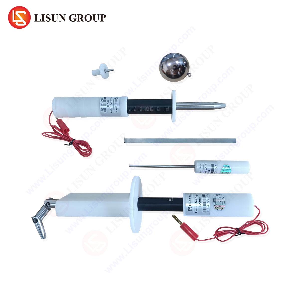
Gauges Figure C4A is not a single gauge but a calibrated set of individual gauges, each engineered to test a specific critical dimension or safety feature of a plug or socket. The assembly is typically constructed from high-grade, hardened tool steel or similarly durable materials that resist wear, corrosion, and deformation over thousands of cycles. This material selection is paramount to maintaining gauge integrity and ensuring long-term measurement traceability. The assembly’s architecture is modular, allowing for the independent use of each gauge component. Key elements of the C4A assembly often include a plug gauge, a socket gauge, a contact pin gauge, and specialized check pins for earth and line/neutral contacts. Each component is machined to the maximum or minimum material condition as defined by the relevant standard, creating a perfect geometric inverse of the allowable limits for the device under test.
Interpreting the Gauge Set: A Functional Decomposition
Understanding the function of each gauge within the C4A set is essential for proper application. The plug gauge, for instance, is manufactured to the maximum allowable dimensions of a standard plug. A compliant plug must fit freely into this gauge without binding or requiring excessive force, verifying that it will not be too large for a standardized socket. Conversely, the socket gauge is crafted to the minimum allowable internal dimensions. A compliant socket must accept this gauge, confirming that its internal receptacle is not too small to accommodate a standardized plug. Furthermore, the set includes pin gauges for the individual live, neutral, and earth pins. These are precision-ground cylinders with diameters at the maximum and minimum tolerance limits. The “go” gauge must enter the pin hole, while the “no-go” gauge must not, thereby verifying the pin’s diameter is within specification. This binary testing methodology eliminates subjective interpretation and provides unambiguous results.
The Verification Protocol for Socket Outlets
The application of the
Gauges Figure C4A to a socket outlet involves a multi-stage verification protocol. The initial step typically involves the use of the socket gauge. The technician attempts to insert the gauge into the socket outlet with a specified force, as defined by the standard (e.g., a maximum of 40 Newtons). Successful insertion confirms that the socket’s internal dimensions are sufficiently large. Subsequent steps involve testing the shutter mechanism, a critical safety feature in many modern sockets designed to prevent the insertion of foreign objects. Specialized gauges from the set, often simulating a single pin, are used to apply force to the shutters in a defined sequence to ensure they open correctly for a legitimate plug but resist intrusion otherwise. The alignment and depth of the contact tubes are also verified using pin gauges to ensure that live parts are recessed to a safe depth, preventing accidental contact.
Plug Conformity Assessment and Pin Dimensional Analysis
For plug assessment, the C4A set provides an equally rigorous testing regimen. The plug is inserted into the plug gauge to verify its overall form factor does not exceed maximum dimensions. Each pin is then individually assessed. The diameter of the live and neutral pins is checked using the “go/no-go” pin gauges. The earth pin, often being a different size and shape (e.g., rectangular), requires its own dedicated gauge to verify its cross-sectional dimensions and length. The spacing between pin centers is another critical parameter; an incorrect pin span can lead to misalignment with socket contacts, resulting in a high-resistance connection and potential overheating. The C4A set includes a gauge or a method to verify this center-to-center distance, ensuring the plug will align perfectly with the socket’s internal contacts.
Material Science and Wear Compensation in Gauge Design
The long-term accuracy of the
Gauges Figure C4A is a direct function of its material properties and manufacturing process. The use of hardened tool steel provides exceptional resistance to abrasive wear, which is inevitable during repeated insertion and withdrawal cycles. Surface treatments, such as nitriding or chrome plating, can further enhance surface hardness and corrosion resistance, preserving the gauge’s critical dimensions. Furthermore, the design often incorporates wear lands—slightly oversized sections on “no-go” gauges—that are designed to be the first point of contact. This sacrificial design philosophy ensures that the primary measuring surfaces of the gauge remain within tolerance for a longer period, even as the gauge experiences normal operational wear, thereby extending its service life and maintaining calibration integrity.
Traceability and Calibration in Metrological Practice
As a certified reference instrument, the LISUN
Gauges Figure C4A must be part of a rigorous calibration system. Its dimensional accuracy is traceable to national or international measurement standards through an unbroken chain of comparisons. Calibration intervals are typically annual, though this can vary based on usage frequency. During calibration, each gauge component is measured using coordinate measuring machines (CMM) or laser scanners with a measurement uncertainty significantly smaller than the tolerance of the gauge itself. A calibration certificate accompanies the gauge set, documenting the as-found and as-left conditions for each critical dimension, providing legal and technical proof of its conformity. This traceability is non-negotiable in a quality assurance environment, as it validates the entire testing process.
Integration within Automated Quality Control Systems
While traditionally used in manual inspection stations, gauges like the C4A are increasingly being integrated into semi-automated or fully automated quality control systems. In such configurations, robotic arms manipulate the gauge or the device under test. Force sensors are used to precisely apply and measure the insertion force, removing human variability from the test. Vision systems can be employed to guide the gauge and verify alignment. The “go/no-go” result is then fed directly into a statistical process control (SPC) system, allowing for real-time monitoring of production line trends and the immediate flagging of dimensional drift in manufactured components before it results in a non-conforming batch. This integration represents the evolution of gauge use from a simple inspection tool to a core component of a data-driven manufacturing intelligence platform.
Comparative Analysis with Dimensional Measurement Alternatives
It is pertinent to contrast the gauge-based “go/no-go” methodology with alternative dimensional measurement systems, such as optical scanners or CMMs. While these systems provide rich, high-resolution data and can generate full 3D models of a component, they are often slower, more complex to operate, and significantly more expensive than a gauge set. The primary advantage of the
Gauges Figure C4A is its speed, simplicity, and direct linkage to the standard’s requirements. It answers the fundamental question of compliance instantly, without requiring sophisticated data interpretation. For high-volume production environments where 100% inspection of critical safety dimensions is required, the robustness and speed of a dedicated gauge set are unparalleled. CMMs are better suited for first-article inspection or failure analysis, whereas gauges are the workhorse of the production floor.
Case Study: Mitigating Pin Deformation in High-Volume Plug Production
A practical application of the
Gauges Figure C4A can be observed in a high-volume plug manufacturing facility. The production process involved injection molding of the plug body and machining of the brass contact pins. The quality control team, using the C4A set for routine batch inspection, began to observe an increasing rate of “no-go” failures on the live pin diameter. The gauge provided an immediate, unambiguous signal of a process deviation. Investigation traced the issue to a slight wear in the pin machining tool, causing a trend toward the maximum tolerance limit. Because the gauge-based SPC system detected this trend early, the tool was replaced during a scheduled maintenance window, avoiding the production of an entire batch of non-compliant plugs that would have required scrapping. This case underscores the role of the gauge not just as a quality gate but as a proactive process control tool.
Regulatory Frameworks and Standards Conformance
The design and application of the
Gauges Figure C4A are inextricably linked to a specific regulatory framework. Its dimensions are derived directly from the requirements of standards such as BS 1363, IEC 60884-1, or other relevant specifications for plugs and socket-outlets. It is crucial that the gauge set is certified to be in conformity with the latest amendment of the target standard. Manufacturers must ensure that their quality control laboratories are using the correct gauge revision for the standard against which they are certifying their products. The use of an obsolete or non-conforming gauge can lead to false approvals or unnecessary rejections, with significant financial and legal repercussions. The LISUN C4A is engineered and certified to provide this essential link between the abstract language of a standard and the physical reality of a manufactured product.
Economic Impact of Precision Gauge Implementation
The deployment of a rigorous gauge-based inspection system, centered on instruments like the C4A, has a direct and positive economic impact on a manufacturing operation. The most obvious benefit is the prevention of costly recalls, returns, and liability claims associated with non-compliant products. Furthermore, by ensuring component interoperability, it reduces field failure rates and enhances brand reputation. Internally, it minimizes production line downtime caused by misaligned components during final assembly. The early detection of tooling wear, as illustrated in the previous case study, allows for predictive maintenance, optimizing tool life and preventing the waste of raw materials. The initial capital investment in a certified gauge set is rapidly offset by the avoidance of these far greater costs, establishing it as an essential asset for any serious manufacturer in the electrical components industry.
Frequently Asked Questions (FAQ)
Q1: How does the “go/no-go” principle of the C4A gauge ensure safety beyond just physical dimensions?
The “go/no-go” test is a holistic safety check. For example, a plug that fails the “go” gauge test for pin diameter may still make electrical contact, but the connection could be loose. A loose connection leads to a high contact resistance, which generates excessive heat under load, potentially causing insulation melting, fire, or socket degradation. The gauge, therefore, indirectly verifies the electrical performance and thermal safety of the connection by ensuring a precise mechanical fit.
Q2: What environmental controls are necessary for the storage and use of the C4A gauge set to maintain its accuracy?
The gauge set should be stored in a controlled environment with stable temperature and low humidity to prevent thermal expansion and corrosion. The standard reference temperature for dimensional metrology is 20°C (68°F). While the steel’s coefficient of thermal expansion is low, significant temperature swings can introduce measurable error when working with tight tolerances. Furthermore, the gauges should be handled with clean gloves to prevent acidic perspiration from causing surface corrosion and stored in individual protective cases to avoid nicks or dings.
Q3: Can the C4A gauge set be used to diagnose the root cause of a molding or machining defect, or does it only identify a failure?
While it primarily identifies a failure, the specific gauge that fails can provide strong diagnostic clues. A failure with the overall plug gauge suggests an issue with the mold cavity for the plug body. A failure with a specific pin gauge points directly to the tooling for that pin. A failure with the socket gauge but not the plug gauge indicates a problem with the socket molding process or its internal contact alignment. Thus, the gauge set is a powerful first-tier diagnostic tool.
Q4: How frequently should the gauge set be calibrated, and what happens if it fails its own calibration?
Calibration frequency is typically annual but should be based on usage. A gauge used for 100% inspection on three shifts should be calibrated more frequently than one used for spot checks. If a gauge fails calibration, it means its dimensions have drifted outside the permissible tolerance. All products tested since the gauge’s last successful calibration become suspect and should be quarantined and re-evaluated with a certified gauge. The failed gauge must be taken out of service for rework or replacement.