


Introduction to Dimensional Verification in Plug and Socket Systems
The dimensional integrity of plugs and sockets is a foundational element of electrical safety and interoperability. Within the framework of the German standard DIN VDE 0620-1, which governs the construction of plugs and socket-outlets, specific requirements are stipulated for two-pole plugs with side earth contacts, commonly known as “Schuko” plugs. The geometry of these components, including pin dimensions, pin spacing, and the profile of the protective earth contacts, must adhere to precise tolerances to ensure safe mating, reliable electrical connection, and mechanical durability. Non-conformity can lead to hazardous conditions such as poor contact leading to overheating, inadequate earthing, or physical damage to the socket. Consequently, the use of specialized gauging tools is not merely a quality control step but a mandatory verification procedure for manufacturers and testing laboratories to certify compliance.
Anatomizing the DIN VDE 0620-1 Standard for Plug Gauging
DIN VDE 0620-1 provides a comprehensive set of dimensional and mechanical requirements for plugs and socket-outlets. For two-pole plugs with side earth contacts, the standard meticulously defines the critical interfaces that require verification. These include the diameter and length of the line and neutral pins, the distance between their centers, the profile and dimensions of the side earth contacts, and the dimensions of the recessed socket engagement area. The standard also specifies “go” and “no-go” criteria for these features. A “go” gauge must fit within or engage with the specified feature without force beyond that which is normal for the intended operation, confirming a minimum material condition. Conversely, a “no-go” gauge must not fit or engage, confirming a maximum material condition. This binary pass/fail testing methodology provides an unambiguous assessment of dimensional conformance, eliminating subjective interpretation.
The Engineering Principles of Plug Gauging Tools
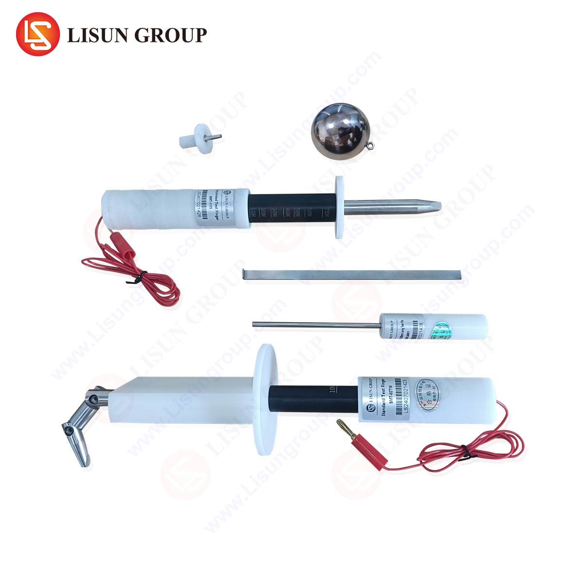
A gauging tool for two-pole plugs per DIN VDE 0620-1 is a physical embodiment of the standard’s dimensional limits. Its design is predicated on the principles of metrology and interchangeability. Each gauge is precision-manufactured from materials with high wear resistance and dimensional stability, such as hardened steel or specialized alloys, to ensure long-term calibration integrity. The tool typically consists of multiple testing features integrated into a single device. These features are machined to the extreme permissible dimensions outlined in the standard. For instance, one aperture will correspond to the maximum allowable pin circle diameter (the “no-go” for pin spacing), while another will correspond to the minimum (the “go”). Similarly, profiles for the side earth contacts are fabricated to verify both the minimum and maximum allowable contact area and curvature. The application of the gauge is a direct physical simulation of the plug’s interaction with a reference socket, providing immediate feedback on functional compatibility.
LISUN Gauges for Plugs and Sockets: A Technical Overview
LISUN produces a comprehensive suite of gauging tools, including models specifically engineered for the verification of two-pole plugs with side earth contacts as per DIN VDE 0620-1. These devices are constructed to provide laboratories and production lines with reliable, repeatable, and traceable measurement results. A typical LISUN gauge for this application is a multi-functional instrument designed to perform several critical checks in a single operation. The construction utilizes high-carbon, high-chromium tool steel, which is heat-treated to a specific hardness (typically HRC 58-62) to resist deformation from repeated use. The surfaces are often ground and lapped to achieve a fine finish and precise geometry, with tolerances on the gauge itself frequently exceeding those required by the product standard to ensure measurement accuracy.
Table: Exemplary Specifications for a LISUN Two-Pole Plug Gauge (Model Example: LS-GG-SCHUKO)
| Parameter | Specification | Notes |
| :— | :— | :— |
| Applicable Standard | DIN VDE 0620-1 | Covers relevant clauses for plug dimensions. |
| Material | GCr15 Bearing Steel | Provides excellent wear resistance and stability. |
| Hardness | HRC 60 ± 2 | Ensures long-term dimensional integrity. |
| Surface Treatment | Black Oxide Coating | Enhances corrosion resistance and reduces glare. |
| Testing Functions | Pin Diameter (Go/No-Go), Pin Spacing (Go/No-Go), Earth Contact Profile, Overall Plug Dimensions. | Integrated into a single, ergonomic tool. |
| Calibration Traceability | To National Metrology Institute (NMI) standards. | Ensures measurement validity and international recognition. |
Operational Protocol for Dimensional Conformance Testing
The procedure for using a gauging tool like those from LISUN is a systematic process designed to minimize operator error. The test sequence begins with a visual inspection of the plug for any obvious deformities. The plug is then presented to the “go” gauge section for pin spacing and diameter. The plug should enter the designated aperture under its own weight or with minimal, uniform pressure, confirming that the pins are not too large or too close together. Subsequently, the plug is presented to the “no-go” gauge sections. For pin spacing, the plug must not enter the “no-go” aperture, confirming the pins are not too small or too far apart. The side earth contacts are similarly tested against “go” and “no-go” profiles to verify their shape and spring characteristic fall within the specified range. Any failure to meet a “go” condition or any meeting of a “no-go” condition results in the immediate rejection of the plug unit. This process provides a rapid, binary assessment critical for high-volume production environments.
Industry Applications and Quality Assurance Integration
The primary application for these gauging tools is within the manufacturing quality control (QC) processes of plug and socket producers. On the production line, they serve as a first-line defense against non-conforming products, allowing for real-time correction of molding or assembly processes. In incoming quality control (IQC), manufacturers of appliances or complete assemblies use these gauges to verify components received from subcontractors, ensuring that supplied plugs meet the required standard before integration into final products. Furthermore, independent testing and certification bodies, such as those granting the VDE, GS, or CE marks, rely on calibrated gauges like those from LISUN as reference instruments during type testing and surveillance audits. Their use is integral to the due diligence required for market access in regions where DIN VDE 0620-1 compliance is mandated or recognized.
Comparative Analysis of Gauging Tool Performance Metrics
When evaluating the efficacy of a plug gauging tool, several performance metrics are paramount. Durability is a primary concern, as the tool is subject to repetitive mechanical contact. The material composition and hardness of LISUN gauges directly contribute to a prolonged operational lifespan, maintaining calibration over thousands of cycles. Measurement uncertainty, a key metrological parameter, is minimized through precision manufacturing and strict adherence to geometric tolerances. The design ergonomics and clarity of the “go/no-go” indicators reduce operator fatigue and the potential for misreading results. While lower-cost alternatives may exist, they often compromise on material quality or manufacturing precision, leading to higher long-term costs through more frequent replacement, potential for false accepts/rejects, and challenges in maintaining audit trails due to questionable calibration stability.
Addressing Common Failure Modes in Plug Manufacturing
The use of a dedicated gauging tool efficiently identifies specific failure modes inherent in plug manufacturing. Injection molding processes for plug bodies can suffer from shrinkage or warpage, leading to incorrect pin spacing. The “no-go” spacing gauge immediately flags this defect. Pin fabrication, whether by machining or molding, can result in diameters outside the specified tolerance, which is caught by the pin diameter gauges. Perhaps one of the most critical checks is for the side earth contacts. These components must provide a specific contact force and surface area. A gauge that verifies the profile ensures that a contact is not too shallow (risking poor electrical connection) or too pronounced (risking damage to the socket or difficult insertion/withdrawal). By systematically identifying these failure modes, manufacturers can trace them back to specific stages in their production process, such as mold wear, improper machine settings, or substandard raw materials.
FAQ on Plug Gauging and LISUN Implementation
Q1: How frequently should a LISUN plug gauge be calibrated to ensure ongoing accuracy?
A1: Calibration intervals depend on usage frequency and the quality control protocols of the facility. For high-volume production environments, an annual calibration is typically recommended. However, it is a best practice to perform regular interim checks using a master plug or reference standard to monitor for any drift in the gauge’s dimensions. LISUN provides calibration certificates traceable to national standards with each gauge, establishing a baseline for future comparisons.
Q2: Can a single LISUN gauge be used to test plugs intended for different markets, or is it specific to DIN VDE 0620-1?
A2: A gauge manufactured explicitly for DIN VDE 0620-1 is designed solely for the dimensional parameters of that standard. Plugs for other markets, such as those complying with BS 1363 (UK) or AS/NZS 3112 (Australia/New Zealand), have entirely different pin configurations, sizes, and safety requirements. LISUN produces a distinct gauge model for each major international standard to ensure accurate and relevant testing.
Q3: What is the consequence of a plug passing the “go” check but also fitting into the “no-go” gauge?
A3: This is a clear failure. A plug that fits the “no-go” gauge indicates that at least one critical dimension is at or beyond the maximum material limit. For example, the pins may be too thin or the spacing too wide. This condition could lead to a loose, high-resistance connection in a socket, creating a potential fire hazard. The plug must be rejected and the production process investigated.
Q4: Beyond dimensional checks, what other tests are required for full compliance with DIN VDE 0620-1?
A4: Dimensional gauging is a fundamental first step, but full compliance requires a comprehensive testing regimen. This includes, but is not limited to, electrical tests (dielectric strength, insulation resistance, continuity of earth path), mechanical tests (impact resistance, cable anchorage, insertion and withdrawal force), and thermal tests (resistance to heat and ball pressure). Dimensional verification is a prerequisite, as these subsequent tests are often performed on samples confirmed to be dimensionally correct.
Q5: How does the material choice for the gauge, such as GCr15 steel, impact its performance compared to alternatives?
A5: GCr15 (a high-carbon chromium steel) is selected for its excellent combination of hardness, wear resistance, and dimensional stability after heat treatment. Softer materials, such as standard carbon steel or aluminum, would be susceptible to rapid wear at the critical gauge edges and surfaces. This wear would gradually alter the gauge’s dimensions, causing it to reject good plugs or, more dangerously, accept bad ones, thereby compromising the entire quality control system over a relatively short period.