


Evaluating Fire Hazard Resistance: The Glow-Wire Endurance Test in Product Safety Engineering
Introduction to Thermal Stress Testing for Ignition Resistance
Within the rigorous landscape of product safety evaluation, the simulation of thermal fault conditions represents a critical frontier. The Glow-Wire Endurance Test (GWET) stands as a preeminent methodology for assessing the ignition resistance of materials and components when subjected to a controlled heat source. This procedure is not an examination of flammability under open flame, but rather a sophisticated evaluation of a product’s ability to withstand thermal stress from overheating elements—a common failure mode in electrical systems. The test’s primary objective is to determine whether a test specimen will ignite, and if so, to measure the duration and consequences of such ignition, including the production of flaming droplets or particles that could propagate fire. Its application spans industries where electrical safety is non-negotiable, from the microelectronics in medical devices to the high-current systems in automotive applications. By imposing a repeatable and severe thermal insult, the GWET provides quantifiable data that informs material selection, design geometry, and compliance with international safety standards, thereby serving as a fundamental barrier against fire hazards originating from electrical equipment.
Fundamental Principles and Governing Standards of the Glow-Wire Method
The operational principle of the Glow-Wire Endurance Test is deceptively straightforward yet scientifically robust. A standardized heating element, the “glow-wire,” constructed from a nickel/chromium (Ni/Cr) alloy with a specified diameter, is heated electrically to a precise temperature, typically ranging from 550°C to 960°C, as defined by the applicable standard. This pre-heated element is then brought into contact, under a defined force (1.0 N ± 0.2 N), with the test specimen for a predetermined period, usually 30 seconds. The test apparatus meticulously controls three key parameters: glow-wire temperature, application force, and duration of contact.
The test’s procedural rigor is dictated by internationally recognized standards, primarily the IEC 60695-2-10 series (and its national equivalents, such as UL 746A and GB/T 5169.10). These documents provide the exhaustive framework for test equipment calibration, specimen preparation, test environment, and pass/fail criteria. The criteria are multifaceted. A specimen is deemed to have passed if: no ignition occurs; flames or glowing of the specimen extinguish within 30 seconds after removal of the glow-wire, and any surrounding tissue paper (used to detect flaming droplets) is not ignited by falling particles. Failure is indicated by sustained flaming combustion exceeding 30 seconds post-application or the ignition of the indicator tissue. The selection of the test temperature is not arbitrary; it is derived from the product’s intended use, its fault current ratings, and its proximity to other components, making the GWET a risk-assessment-driven exercise.
The LISUN ZY-3 Needle-Flame Test Apparatus: A Specialized Instrument for Precision Evaluation
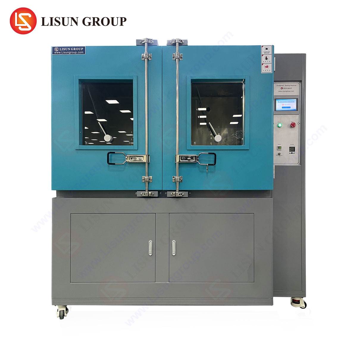
While the classic glow-wire test utilizes a looped heating element, certain standards, particularly those assessing the effects of small flames from faulty components, call for a needle-flame simulation. The LISUN ZY-3 Needle-Flame Test Apparatus is engineered to meet these exacting requirements, conforming to standards such as IEC 60695-11-5, IEC 60695-2-2, and GB/T 5169.5. This instrument is designed to apply a small, reproducible test flame to a specimen to assess its fire hazard under simulated fault conditions.
The ZY-3 apparatus generates its flame via a specific burner fed with a prescribed fuel (typically 99% purity butane). The burner produces a stable flame of 12mm ± 1mm in height, which is applied to the test specimen at a defined angle (45° or 90°, as per standard) for a set exposure time (e.g., 5, 10, 20, 30, 60, or 120 seconds). The core testing principle mirrors that of the glow-wire in its observational focus: it monitors whether the specimen ignites, the duration of any subsequent flaming, and whether burning droplets ignite a specified layer of surgical cotton placed beneath the specimen.
Key Specifications of the LISUN ZY-3 Apparatus:
- Flame Height Adjustment: Precise mechanical or gauge-based adjustment to maintain the 12mm ± 1mm requirement.
- Timing Range: Programmable application and observation timers, typically from 0 to 999.9 seconds, with an accuracy of ±0.1s.
- Burner Positioning: Micrometer-adjusted sliding rails and rotating specimen holder allow for precise and repeatable positioning of the flame relative to the specimen’s most vulnerable point.
- Safety Features: Integrated ventilation systems for fume extraction, flame-out protection, and gas leakage alarms.
- Calibration: Includes tools for verifying flame temperature and dimensions using a dedicated thermocouple and height gauge.
The ZY-3’s design emphasizes repeatability and user safety. Its automated timing and positioning functions minimize operator variance, a critical factor in generating reliable, audit-ready test data. The inclusion of a transparent observation chamber with fume extraction allows for safe monitoring of the test progression.
Industry-Specific Applications and Risk Mitigation Scenarios
The Glow-Wire and Needle-Flame tests are applied across a diverse spectrum of industries, each with unique failure modes and consequences.
- Household Appliances & Consumer Electronics: For devices like power supplies, chargers, motor controllers in food processors, or internal wiring harnesses in televisions, the test evaluates plastic enclosures and internal barriers. A failed test might reveal that a transformer’s housing could ignite if a nearby resistor overheats, leading to a redesign with a higher-temperature-rated polymer.
- Automotive Electronics: In the confined, vibration-prone, and thermally challenging environment of a vehicle, components like electronic control units (ECUs), battery management systems, and lighting modules are subjected to GWET. The test validates that a short-circuit within a headlight control module will not cause the lens or housing to sustain a flame.
- Lighting Fixtures: LED drivers, plastic diffusers, and socket housings are tested to ensure that a fault in the driver’s circuitry does not result in the ignition of the luminaire, which is often installed in ceilings where fire spread is a significant concern.
- Medical Devices: For patient-connected equipment such as infusion pumps or monitoring devices, the use of flame-retardant materials validated by needle-flame testing is crucial. It ensures that a catastrophic internal electrical fault does not generate an external fire hazard in an oxygen-rich clinical environment.
- Aerospace and Aviation Components: Every gram matters, yet safety is paramount. GWET helps select lightweight polymer composites for cabin entertainment systems, overhead panel switches, and wiring conduits that must resist ignition from an overheated wire bundle without adding excessive weight.
- Telecommunications & Industrial Control: Data servers, routers, PLCs, and switchgear often operate 24/7. The test assesses bus bars, relay housings, and connector blocks to prevent a single component failure from cascading into a cabinet fire.
Interpreting Test Results: From Raw Data to Design Insight
The output of a Glow-Wire or Needle-Flame test is more than a simple pass/fail notation. A comprehensive analysis provides deep engineering insights. The time-to-ignition (TTI), if ignition occurs, is a critical material property. A longer TTI indicates a higher resistance to the specific thermal insult. The duration of flaming after the removal of the heat source is directly related to the material’s self-extinguishing properties.
The production of flaming droplets is a particularly hazardous result, as it represents a mechanism for fire propagation beyond the origin. Observing the pattern and ignition capability of these droplets informs decisions about the use of drip trays, barriers, or material formulations that reduce melt flow. For example, a glass-filled polymer may resist ignition but produce fewer, less-flammant droplets compared to an unfilled counterpart.
Data is often compiled into tables for comparative analysis:
Table 1: Example Glow-Wire Test Results for Enclosure Materials
| Material Grade | Test Temp. (°C) | Ignition (Y/N) | Flaming Time (s) | Flaming Droplets? | Tissue Ignited? | GWT Pass/Fail |
| :— | :— | :— | :— | :— | :— | :— |
| ABS (Unmodified) | 750 | Yes | 45 | Yes | Yes | Fail |
| Flame-Retardant ABS | 750 | No | 0 | No | No | Pass |
| Polycarbonate | 850 | Yes | 12 | Minimal | No | Pass* |
| PBT with 30% GF | 850 | No | 0 | No | No | Pass |
*Passes as flaming extinguished within 30s and no tissue ignition.
This data directly guides design: an unmodified ABS enclosure for a power strip would fail; a switch to a flame-retardant grade or a redesign with a metal shield might be necessary.
Operational Protocol and Critical Factors Influencing Test Outcome
The reproducibility of the GWET hinges on strict adherence to a controlled protocol. Key operational steps include:
- Conditioning: Specimens must be conditioned in a standard atmosphere (e.g., 23°C ± 2°C, 50% ± 5% RH) for a minimum period (often 48 hours) prior to testing to eliminate moisture effects.
- Calibration: The glow-wire or needle-flame apparatus must be calibrated using reference materials, such as tin and silver foils for temperature verification, before any test series.
- Specimen Mounting: The specimen is mounted in a representative manner. A switch, for instance, is tested as a complete unit in its housing, not just the plastic material in a plaque form.
- Application: The heat source is applied to the “worst-case” location, often determined by a pre-test assessment of wall thickness, proximity to internal heat sources, or material junctions.
- Observation & Measurement: Trained operators record the precise timing of ignition, flame duration, and droplet behavior. High-speed video recording is frequently employed for post-test analysis.
Factors that can significantly influence results include:
- Wall Thickness: Thinner sections heat through more quickly and are more likely to ignite and produce droplets.
- Part Geometry: Ribs, bosses, and corners can concentrate heat or promote dripping.
- Material Composition: Fillers (like glass or minerals) and flame retardant additives (halogenated, phosphorus-based, or mineral) dramatically alter thermal and combustion behavior.
- Internal Air Gaps: Air pockets within an assembly can act as insulators or, conversely, allow for pre-heating of adjacent surfaces.
Comparative Analysis: Glow-Wire Versus Alternative Fire Hazard Tests
The GWET occupies a specific niche within the broader suite of fire safety tests. It is distinct from, yet complementary to, other common evaluations:
- Horizontal/Vertical Flame Tests (e.g., UL 94): These assess the flammability of a material strip under a small flame. UL 94 is a material screening test, while GWET is a product-oriented simulation test. A material may achieve a V-0 rating in UL 94 but fail a GWET at 750°C due to the more severe and localized energy input of the glow-wire.
- Hot-Wire Coil Ignition Test (HWI): This test wraps a heated wire around a specimen to simulate overheating in a current-carrying component. It is more specific to situations where the component itself is the heat source, whereas GWET simulates an external overheated part.
- Needle-Flame Test: As implemented by the LISUN ZY-3, this is a more direct flame impingement test than the glow-wire’s contact heating. It is often specified for situations where a small, open flame from a burning component is the credible risk, making it highly relevant for low-voltage, high-density electronic assemblies.
The choice of test is dictated by the hazard analysis. A circuit breaker might be evaluated with GWET for external fault exposure and HWI for internal fault exposure.
Integrating Test Outcomes into the Product Development Lifecycle
Effective use of thermal ignition testing is proactive, not merely a compliance checkpoint at the end of development. Integrating GWET and needle-flame evaluations into the design process follows a logical sequence:
- Concept Phase: Preliminary material selection based on published Glow-Wire Ignition Temperature (GWIT) data from suppliers.
- Prototype Phase: Testing of early prototypes using instruments like the LISUN ZY-3 to identify clear failure points—such as a specific connector or vent design—when subjected to a needle-flame.
- Design Validation Phase: Formal testing of production-intent samples to the full GWET protocol at the specified severity to verify compliance.
- Production Change Management: Re-testing whenever a material supplier, grade, or critical component is changed, as minor variations can alter fire performance.
This integration ensures that fire safety is designed-in, avoiding costly last-minute redesigns and ensuring a robust, certifiable final product. It transforms the test from a gate into a guiding tool for engineering decisions.
Frequently Asked Questions (FAQ)
Q1: What is the main difference between the LISUN ZY-3 Needle-Flame Test and a standard Glow-Wire test?
The primary difference lies in the heat source and simulation. The standard Glow-Wire Test uses an electrically heated loop to simulate contact with an overheated solid element. The LISUN ZY-3 applies a small, defined gas flame (a needle-flame) to simulate ignition from a small, open flame, such as that from a burning printed circuit board or a short-circuited component. The test principles and observational criteria are similar, but the applied hazard is different.
Q2: How do I determine the correct test temperature for my product’s Glow-Wire Endurance Test?
The test temperature is not chosen arbitrarily but is mandated by the relevant product safety standard applicable to your equipment. For example, IEC 60335-1 for household appliances specifies different glow-wire test temperatures for parts carrying current in normal use versus those that are only live under fault conditions. The standard will define temperatures based on the estimated fault power or the part’s function. Always consult the specific end-product standard.
Q3: Can the LISUN ZY-3 apparatus be used for both needle-flame and other flame tests?
The LISUN ZY-3 is specifically designed and calibrated to meet the needle-flame test requirements of standards like IEC 60695-11-5. While it produces a small flame, its calibration, burner design, and positioning fixtures are optimized for this specific protocol. It is not a general-purpose Bunsen burner apparatus and should not be used for other flame tests (like UL 94) without ensuring the apparatus configuration and calibration meet those distinct standards.
Q4: My material supplier provides a GWIT (Glow-Wire Ignition Temperature). Is this sufficient for compliance?
A material’s GWIT is a useful screening tool and indicates the temperature at which the material ignites under test conditions. However, product compliance is almost always based on testing the final assembly or a representative sub-assembly (the Glow-Wire Endurance Test, GWT). The finished product’s geometry, wall thickness, internal air gaps, and assembly stresses can all affect performance. Therefore, while GWIT data informs selection, formal compliance requires testing the product as it will be used.
Q5: What are the most common reasons for test failure, and what are the typical remediation steps?
Common failures include sustained flaming (>30s) and ignition of the indicator tissue by droplets. Remediation strategies are tiered: First, consider material substitution to a higher-performance, flame-retardant grade. Second, implement design modifications such as increasing wall thickness at the test point, adding internal metallic heat shields or barriers, or redesigning features to prevent the pooling of molten material. Third, consider the use of flame-retardant coatings or tapes as a last resort, though their long-term adhesion and durability must be validated.