


Evaluating Fire Hazard Resistance: The Glow-Wire Test in Material and Component Qualification
The relentless miniaturization and increased power density of modern electrical and electronic components have elevated fire safety from a secondary consideration to a primary design imperative. A single overheated connection, a failed semiconductor, or a degraded insulating material can act as an ignition source, potentially leading to catastrophic failure within an enclosure. To mitigate these risks, standardized simulation tests are employed to evaluate the ignition resistance and flame-retardant properties of materials and assemblies. Among these, the Glow-Wire Test stands as a critical, internationally recognized method for assessing the ability of insulating materials and other solid electrical parts to withstand thermal stresses caused by overheated or glowing components.
This test does not evaluate flammability in the traditional sense of exposure to an open flame. Instead, it simulates a more insidious and common fault condition: the thermal effect of an overloaded or faulty resistive element, such as a wirewound resistor, a poor connection, or an overheating switch contact, in close proximity to non-metallic materials. The test provides a quantifiable measure of a material’s resistance to ignition and its propensity to spread flame, offering invaluable data for engineers, material scientists, and compliance officers across safety-critical industries.
The Thermodynamic Principles of Glow-Wire Simulation
The fundamental principle of the Glow-Wire Test is the application of a precisely controlled thermal energy source to a test specimen. A resistance wire element, typically constructed from a nickel/chromium (Ni/Cr) alloy, is heated electrically to a specified test temperature, which can range from 550°C to 960°C depending on the applicable standard and required severity level. This heated element, the “glow-wire,” is then brought into contact with the test specimen under a defined force of 1.0 N ± 0.2 N for a period of 30 seconds ± 1 second.
The interaction is a complex thermodynamic event. Energy is transferred from the glow-wire to the specimen via conduction, convection, and radiation. The material’s response is governed by its thermal conductivity, specific heat capacity, decomposition temperature, and the heat of combustion of its volatile pyrolysis products. A material may exhibit several behaviors: it may not ignite; it may ignite but self-extinguish within a specified time after removal of the glow-wire; or it may sustain burning and ignite a tissue paper indicator placed below, signifying a failure. The test thus measures not just ignition propensity but also the duration and severity of any subsequent combustion.
Standards Framework and Industry-Specific Applications
The Glow-Wire Test is codified in several key international standards, primarily the IEC 60695-2 series. IEC 60695-2-10 outlines the general apparatus and test method, while IEC 60695-2-11 defines the test method for end products (GWEPT) and IEC 60695-2-12 for materials (GWT). Harmonized standards such as EN 60695-2 and UL 746A provide regional compliance pathways. These standards are invoked by a vast array of product-specific safety standards, making the test a ubiquitous requirement.
Its application is pervasive across industries where electrical safety is non-negotiable:
- Electrical and Electronic Equipment & Industrial Control Systems: Enclosures, terminal blocks, PCB substrates, and insulator housings are tested to ensure a faulty internal component cannot ignite the apparatus.
- Household Appliances and Consumer Electronics: Switches, connectors, internal supports, and external casings for devices like coffee makers, power adapters, and televisions are subject to glow-wire evaluation.
- Automotive Electronics: Under-hood components, battery management system housings, and wiring harness supports must resist ignition from potential short-circuit events in the harsh automotive environment.
- Lighting Fixtures: Lamp holders, control gear housings, and diffuser materials, especially in LED drivers which can generate significant heat, are common test subjects.
- Telecommunications Equipment: Data server components, router casings, and power supply units in always-on infrastructure require high glow-wire endurance.
- Medical Devices and Aerospace Components: For patient-connected equipment and aviation electronics, the test severity is often increased, with materials required to withstand higher glow-wire temperatures to meet stringent failure mode and effects analysis (FMEA) requirements.
- Electrical Components and Cable Systems: Switches, sockets, and the insulation of wiring systems are directly tested, as they are the most likely points of overheating.
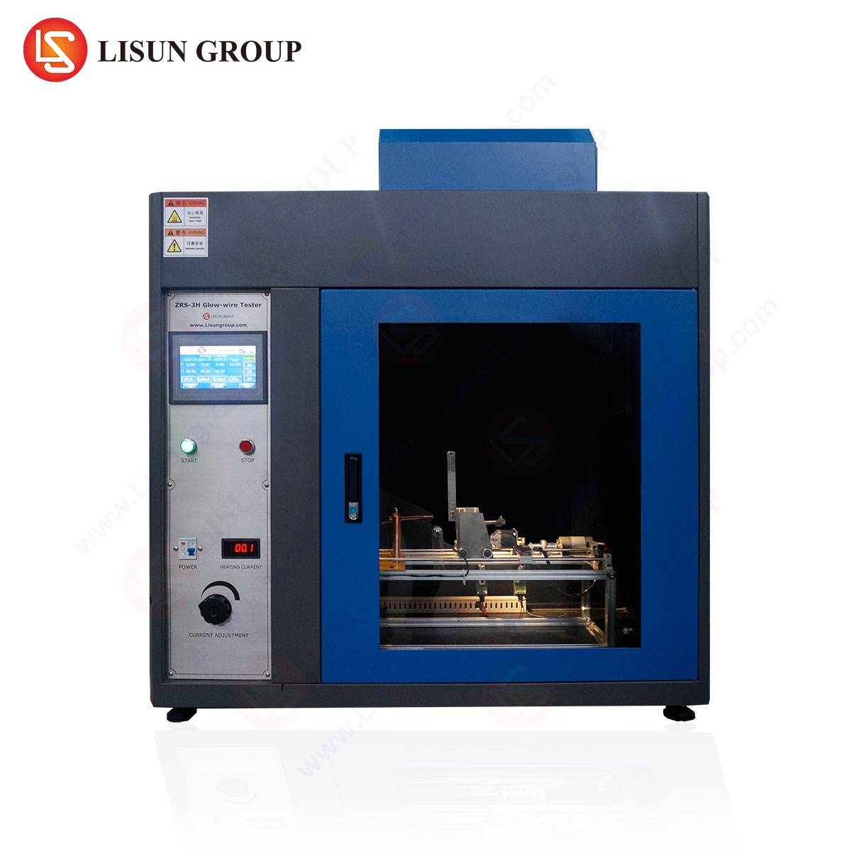
Instrumentation for Precision: The LISUN ZY-3 Needle Flame Test Apparatus
Accurate and reproducible Glow-Wire testing demands instrumentation of exceptional precision, stability, and compliance. The LISUN ZY-3 Needle Flame Test apparatus is engineered to meet and exceed the exacting requirements of IEC 60695-2, IEC 60695-11-5, and related standards. While its designation references “Needle Flame,” its design and functionality comprehensively cover the glow-wire methodology, providing a versatile platform for fire hazard assessment.
The core of the ZY-3 system is its digitally-controlled heating circuit. A microprocessor-based controller regulates current flow to the glow-wire, enabling precise temperature setting and stability from 100°C to 1000°C with a resolution of 1°C. This closed-loop control is critical, as a deviation of just 10°C can significantly alter test outcomes. The apparatus features a calibrated K-type thermocouple spot-welded to the glow-wire tip, providing real-time feedback to the PID controller to maintain temperature within ±2°C of the setpoint, a tolerance stricter than that demanded by many standards.
Key Technical Specifications of the LISUN ZY-3:
- Temperature Range: 100°C ~ 1000°C (continuously adjustable)
- Temperature Control Accuracy: ± 2°C (at 750°C)
- Glow-Wire Application Force: 1.0 N ± 0.2 N, adjustable via calibrated weights
- Test Duration Timer: 0 ~ 99.99 seconds, digital, with automatic retraction
- Flame Application Time (for needle flame): 0 ~ 99.99 seconds
- Specimen Mounting: A multi-adjustable specimen carriage with three-dimensional movement (X, Y, Z axes) for perfect alignment.
- Safety Enclosure: A transparent draft shield with interlock protects the operator and prevents air currents from influencing test results.
- Calibration: Supplied with a certified glow-wire and calibration certificate traceable to national standards.
The testing principle with the ZY-3 involves securing the specimen on the carriage, setting the desired glow-wire temperature and application time via the intuitive interface, and initiating the test. The apparatus automatically advances the heated glow-wire, applies it for the set duration, retracts it, and begins timing for observation of after-flame and after-glow periods. An optional cotton tissue paper indicator and weighing system can be integrated to automatically detect flaming droplets or particles.
Operational Protocol and Data Interpretation
A standardized test procedure is paramount. The specimen, conditioned at 23°C ± 2°C and 50% ± 5% relative humidity for at least 24 hours, is mounted. The glow-wire is heated to the target temperature, verified by the internal thermocouple. After a 60-second stabilization period, it is applied to the thickest part of the specimen (or a predetermined worst-case location) for 30 seconds. Upon retraction, the observer records:
- Duration of after-flame (t₁): The time flaming persists on the specimen.
- Duration of after-glow (t₂): The time the specimen continues to glow after flames cease.
- Ignition of the specimen.
- Ignition of the tissue paper indicator by flaming droplets or particles.
Pass/fail criteria are defined by the invoking product standard. A typical criterion for end products (GWEPT) is that flames or glows on the specimen extinguish within 30 seconds of glow-wire removal, and the tissue paper is not ignited. For materials (GWT), the Glow-Wire Ignition Temperature (GWIT) is determined—the temperature 25°C above the maximum test temperature at which the material does not ignite for more than 5 seconds.
Comparative Advantages in Engineering and Compliance
The LISUN ZY-3 apparatus offers distinct advantages that translate to laboratory efficiency and data integrity. Its primary benefit is metrological precision. The high-accuracy temperature control eliminates a key variable, ensuring tests are reproducible day-to-day and across different operators. This is essential for quality control and for submitting defensible data to certification bodies like UL, TÜV, or Intertek.
Secondly, its robust mechanical construction ensures consistent application force and alignment. The three-axis specimen carriage allows for meticulous positioning, crucial when testing small or irregularly shaped components like miniature automotive connectors or medical device sensor housings. The automated timing and retraction remove operator timing errors, a common source of deviation in manual systems.
Furthermore, the ZY-3’s dual-function design (Glow-Wire and Needle Flame) provides laboratories with a cost-effective, space-saving solution for conducting multiple fire hazard tests as per IEC 60695-11-2, -11-3, -11-4, and -11-5. This versatility is particularly valuable for contract testing labs serving diverse clients from the consumer electronics and electrical components sectors.
Integrating Test Results into the Product Development Lifecycle
Glow-Wire Test data is not merely a compliance checkbox; it is a critical input for the product development lifecycle. In the design phase, screening tests on candidate materials using the GWT method inform material selection, balancing cost, mechanical properties, and fire safety. During prototype validation, GWEPT on complete assemblies or sub-assemblies uncovers unforeseen thermal interactions—for example, how a plastic cable clip inside an industrial inverter might behave if a nearby power resistor overheats.
In failure analysis, the test can replicate field failure modes to validate corrective actions. For instance, if a telecommunications power supply unit failed in the field due to a overheated transformer, the redesigned enclosure can be validated to ensure it now passes the relevant glow-wire severity level. Finally, in production quality assurance, periodic auditing of production parts using the glow-wire test ensures consistency in material formulation and manufacturing processes, safeguarding against long-term reliability degradation.
Conclusion
The Glow-Wire Test remains an indispensable tool in the engineering arsenal for mitigating fire risks in electrical equipment. By realistically simulating a critical overheating fault condition, it provides a quantifiable, standards-based metric for material and product safety. The reliability of the test data is intrinsically linked to the precision and capability of the apparatus used. Instruments like the LISUN ZY-3 Needle Flame Test apparatus, with their emphasis on accurate temperature control, repeatable mechanical application, and operational safety, empower manufacturers across industries—from automotive to aerospace, medical devices to household appliances—to design, validate, and certify products that meet the highest international safety benchmarks, ultimately protecting property and lives.
FAQ Section
Q1: What is the key difference between the Glow-Wire Test (GWT) and the Glow-Wire Flammability Index Test (GWFI)?
The GWT (IEC 60695-2-12) determines the Glow-Wire Ignition Temperature (GWIT)—the temperature at which a material does not ignite. The GWFI (IEC 60695-2-13) determines the highest temperature at which a material does not ignite and does not ignite surrounding tissue paper with droplets. GWIT is about material ignition resistance; GWFI adds a criterion for prevention of fire spread via burning droplets.
Q2: For a new plastic housing for an automotive sensor, at what stage should Glow-Wire testing be performed?
Testing should be integrated at multiple stages. Initially, candidate resin grades should be screened using the material-level GWT to shortlist options. Once a prototype housing is injection-molded, it should undergo end-product testing (GWEPT) per the relevant automotive standard (e.g., ISO 20653 or OEM-specific specifications). Testing should be repeated on production samples to ensure process consistency.
Q3: How often does the glow-wire tip itself need to be replaced or calibrated?
The nickel/chromium glow-wire is a consumable item. It should be replaced whenever it shows visible signs of oxidation, pitting, or deformation, as this will alter its thermal emissivity and contact characteristics. Regular calibration of the entire apparatus, including temperature verification using a traceable reference thermocouple, should be performed annually or as per the laboratory’s quality procedure.
Q4: Can the LISUN ZY-3 test vertically oriented specimens or components with complex geometries?
Yes. The three-dimensionally adjustable specimen carriage allows for precise positioning of specimens in virtually any orientation required by the standard (typically, the glow-wire is applied to a vertical surface). Fixturing can be custom-made to hold irregular components like switches or sockets securely in the correct test position.
Q5: Our product standard requires testing at 750°C. What is the required stabilization time for the glow-wire at this temperature before application?
According to IEC 60695-2-10, after the glow-wire has reached the set test temperature (e.g., 750°C), it must be maintained at that temperature for a period of 60 seconds (± 5 seconds) to ensure thermal equilibrium of the entire wire loop before it is applied to the specimen. The LISUN ZY-3’s controller typically includes a timer for this stabilization phase.