


An Examination of Material Flammability and the Role of Glow Wire Test Equipment
The proliferation of electrical and electronic equipment across global markets has necessitated a rigorous and standardized approach to evaluating fire hazards. A primary concern within industries ranging from household appliances to aerospace components is the resistance of insulating materials to ignition and flame propagation. Among the various testing methodologies developed to assess this risk, the glow wire test has emerged as a critical procedure for simulating thermal stresses that may occur in practice due to overloaded or faulty components. This article provides a detailed analysis of glow wire testing principles, the equipment required for its execution, and its indispensable role in ensuring product safety and regulatory compliance.
Fundamental Principles of the Glow Wire Test Method
The glow wire test is designed to assess the flammability of solid electrical insulating materials or other solid combustible materials by simulating a heat stress condition. The core of the methodology involves a specifically-formulated resistance wire loop, the “glow wire,” which is heated by electrical current to a predetermined temperature, typically within a range of 550°C to 960°C. This heated element is then applied with a defined force to the test specimen for a set period. The test evaluates three primary outcomes: the material’s ability to resist ignition, the duration of any subsequent flaming, and whether dripping particles ignite a surrounding tissue.
The underlying principle replicates a severe but plausible fault condition, such as an overheated resistor, a poor connection, or an overloaded printed circuit board trace. By subjecting a material or sub-assembly to this controlled thermal insult, manufacturers can quantify its fire hazard potential. The test is not a measure of material combustibility in a general sense, but rather a specific assessment of its behavior under a localized, high-temperature exposure. The results are critical for failure mode and effects analysis (FMEA) in the design phase, allowing engineers to select materials that will not propagate fire in the event of an internal fault.
Deconstructing the Glow Wire Test Apparatus: A System Overview
A fully integrated glow wire test apparatus is a sophisticated piece of laboratory equipment comprising several synchronized subsystems. The central component is the glow wire itself, a coiled loop of nickel/chromium wire with a specified composition and dimensions, mounted on a carrier. This carrier is connected to a low-voltage, high-current power supply capable of rapidly and precisely heating the wire to the target temperature, often monitored by a Type K (chromel-alumel) thermocouple silver-brazed to the wire’s surface.
The specimen support system is equally critical. It consists of a mounting bracket and a pressure application mechanism that ensures a reproducible 1.0 N ± 0.2 N force is maintained during the test period. A calibrated copper block with a defined thermal mass is often used to verify the temperature measurement system’s accuracy. The apparatus is housed within a test chamber, typically constructed of heat-resistant and non-conductive materials, to provide a draft-free environment and contain any potential flames. An integrated timing system automatically controls the duration of application, while ancillary equipment, such as a hood and exhaust system, manages combustion products. A key feature of advanced systems is the inclusion of automated flame application and observation, which removes human variability from the ignition and timing processes.
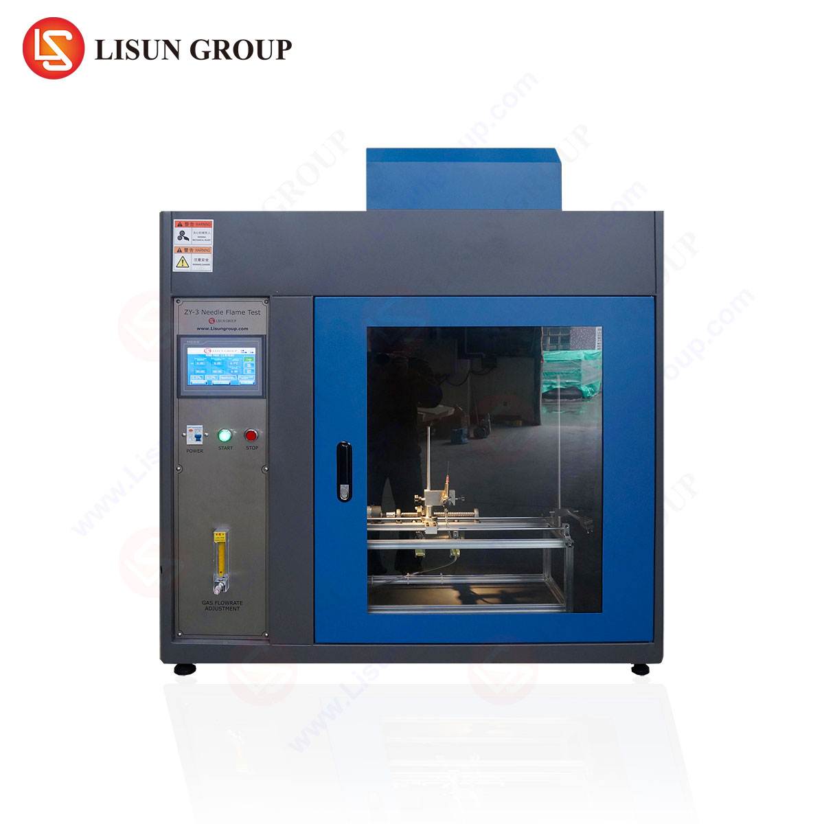
The LISUN ZRS-3H Glow-wire Test Apparatus: Technical Specifications and Operational Fidelity
The LISUN ZRS-3H Glow-wire Test Apparatus represents a contemporary implementation of the standardized test methodology, engineered for precision, repeatability, and user safety. Its design adheres strictly to international standards including IEC 60695-2-10, IEC 60695-2-11, IEC 60695-2-12, IEC 60695-2-13, GB/T 5169.10, GB/T 5169.11, GB/T 5169.12, and GB/T 5169.13, ensuring its applicability in global markets.
Key Specifications of the LISUN ZRS-3H:
- Temperature Range: 500°C to 1000°C, continuously adjustable.
- Temperature Stability: Better than ± 2°C at any point within the range after a brief stabilization period.
- Heating Element: A precision-formed nickel/chromium glow wire.
- Test Duration: Electronically controlled, adjustable from 0 to 99.99 seconds with an accuracy of ± 0.1 seconds.
- Application Force: 1.0 N ± 0.2 N, applied via a calibrated weight and lever system.
- Temperature Measurement: A certified Type K thermocouple integrated into the glow wire assembly, with data displayed on a high-resolution digital indicator.
- Control System: A microcomputer-based programmable logic controller (PLC) and touch-screen Human-Machine Interface (HMI) for intuitive operation, parameter setting, and data logging.
- Safety Features: An enclosed stainless steel test chamber with a transparent, heat-resistant viewing window, an automatic cut-off function, and an integrated fume extraction port.
The operational fidelity of the ZRS-3H is a direct result of its refined engineering. The microcomputer-controlled system ensures that the glow wire is heated to the exact setpoint temperature rapidly and maintained with high stability, a critical factor for test reproducibility. The automated timing and force application eliminate operator-induced errors, while the robust data logging capabilities provide an auditable trail for quality assurance and certification purposes.
Application of Glow Wire Testing Across Industrial Sectors
The utility of glow wire testing spans a vast spectrum of industries where electrical safety is paramount. In each sector, the test is applied to components and enclosures that could be sources of ignition in fault conditions.
- Household Appliances and Consumer Electronics: This is one of the largest application areas. Test subjects include the plastic enclosures of televisions, coffee makers, power adapters, and internal components like motor housings, terminal blocks, and socket outlets. A switch in a washing machine’s control panel, for instance, must withstand a glow wire test to ensure a faulty connection does not set the housing alight.
- Automotive Electronics: The confined and safety-critical nature of vehicles demands high material standards. Glow wire tests are performed on components such as electronic control unit (ECU) housings, connectors, wire insulation, and sensors to prevent fire initiation from electrical faults.
- Lighting Fixtures: Both the plastic bodies of LED drivers and the diffusers or housings of luminaires are tested. The heat generated by the lighting element itself, combined with potential ballast failures, makes this a crucial test.
- Industrial Control Systems and Telecommunications Equipment: Control panels, PLC housings, server rack components, and network switch enclosures are tested to ensure a fault in one component does not lead to a catastrophic failure of the entire system.
- Medical Devices and Aerospace Components: In these highly regulated fields, the consequences of failure are severe. Glow wire testing is applied to the plastic casings of patient monitors, infusion pumps, and non-critical aerospace interior components to verify their resistance to ignition from internal electrical anomalies.
- Electrical Components and Office Equipment: From circuit breakers and power strips to the plastic housings of printers and photocopiers, these ubiquitous products are routinely subjected to glow wire testing as part of their safety certification.
Interpreting Test Results and Ensuring Compliance with Global Standards
The outcome of a glow wire test is not a simple pass/fail but is interpreted based on a multi-faceted observation of the specimen’s behavior during and after the application of the heat source. The criteria for compliance, as detailed in standards like IEC 60695-2-11, are stringent:
- Ignition: The specimen must not ignite during the application of the glow wire.
- Flaming Combustion: If the specimen or any surrounding parts do ignite, the flames must self-extinguish within 30 seconds after removal of the glow wire. Observations are also made for flames or glowing particles falling from the specimen.
- Ignition by Droplets: If the specimen drips, these molten particles must not ignite a single layer of tissue paper (typically surgical cotton) placed 200 mm ± 5 mm below the test specimen.
A test report will typically document the glow wire temperature, the duration of any flames, whether the specimen ignited the tissue paper, and the extent of burning. Compliance is demonstrated when a product’s components meet the specific glow wire flammability index (GWFI) required by the end-product standard. For example, a standard for information technology equipment (ITE) may require that an external enclosure material withstands a test at 750°C, while an internal support for a current-carrying part may need to withstand 850°C.
Comparative Advantages of Modern Automated Test Systems
The transition from manually operated glow wire testers to automated systems like the LISUN ZRS-3H represents a significant advancement in testing quality and laboratory efficiency. The primary advantages are rooted in the elimination of human variables.
Manual systems rely on the operator to observe the test, start and stop timers, and judge the occurrence of ignition and flame duration. This introduces inherent variability and potential for error. Automated systems, in contrast, utilize photoelectric sensors to detect the presence of a flame with millisecond accuracy. The timing is controlled by the internal microprocessor, ensuring the test duration is exact. The result is a dramatic improvement in repeatability and reproducibility (R&R), which are foundational to reliable quality control and successful certification audits. Furthermore, automated systems enhance operator safety by minimizing direct interaction with the high-temperature components and provide robust, time-stamped data records that are indispensable for traceability and defending a product’s compliance.
Frequently Asked Questions (FAQ)
Q1: What is the difference between the Glow-Wire Flammability Index (GWFI) and the Glow-Wire Ignition Temperature (GWIT)?
The GWFI is the highest temperature at which a material does not ignite, or if it does, self-extinguishes within 30 seconds without igniting the tissue paper and does not burn completely. It is a “pass/fail” index for a specific temperature. The GWIT, conversely, is the temperature 25°C above the maximum temperature at which the material does not ignite and does not cause sustained flaming for more than 5 seconds. The GWIT is thus the temperature at which ignition occurs, providing a different, complementary measure of a material’s ignition resistance.
Q2: How often should the glow wire element and thermocouple be calibrated or replaced?
The glow wire and its integrated thermocouple are consumable items subject to oxidation and degradation at high temperatures. Their calibration should be verified before each test series using the reference copper block, as specified in the standard. The frequency of replacement depends on usage, but regular inspection for pitting, deformation, or changes in electrical resistance is mandatory. A significant drift in the temperature verification test indicates the need for immediate replacement to maintain the integrity of test results.
Q3: Can the LISUN ZRS-3H be used for testing non-plastic materials, such as composites or treated textiles?
Yes, the fundamental principle of the test applies to any solid insulating or combustible material used in electrotechnical products. While the standards were developed with plastics in mind, they are frequently applied to composite materials used in automotive or aerospace interiors, as well as to insulating textiles or foams, provided the test is relevant to the real-world failure mode being assessed. The test parameters and pass/fail criteria must be defined by the applicable end-product standard for that material and application.
Q4: What are the critical environmental conditions for conducting a reliable glow wire test?
The test must be performed in a draft-free environment, which is why the apparatus is housed in an enclosed chamber. Ambient temperature and humidity should be recorded, as extreme conditions can theoretically influence results, though the test’s severity often minimizes this effect. Most critically, the laboratory must have adequate ventilation, and the apparatus’s fume extraction system should be operational to safely remove potentially toxic pyrolysis and combustion products generated during testing.