


Introduction to Flammability Assessment in Electrotechnical Products
The proliferation of electrotechnical products across diverse sectors, from domestic environments to critical industrial and medical systems, has necessitated the development of robust safety standards to mitigate fire hazards. Among the most critical evaluations is the assessment of a material’s resistance to ignition and its ability to limit flame propagation when exposed to a heat source simulating thermal stresses encountered in real-world fault conditions. The Glow-Wire Test, standardized internationally under the IEC 60695-2 series, serves as a fundamental methodology for this purpose. This analysis delves into the technical intricacies of glow-wire testing, the critical interpretation of resultant data, and the instrumental role of advanced apparatus like the LISUN ZRS-3H Glow-wire Test Apparatus in ensuring global compliance and product safety.
Deconstructing the Glow-Wire Test Methodology
The core principle of the glow-wire test involves applying a heated element, constructed from a standardized nickel/chromium wire with a specific 4 mm diameter tip, to a test specimen under controlled conditions. This element, the “glow-wire,” is heated by an electric current to a predetermined temperature, calibrated between 550°C and 960°C, depending on the severity of the test required by the end-product standard. The test does not simulate an open flame but rather represents thermal stresses that may arise from overloaded or poorly terminating components, such as a high-resistance connection in a switch or a fault within a power supply unit. The specimen, which can be a final product housing, a material plaque, or a sub-assembly, is subjected to this heat source for a 30-second period. The apparatus must maintain the temperature stability of the glow-wire tip within a tight tolerance, typically ± 10°C, as any deviation can significantly skew the test results and lead to non-compliant products being incorrectly certified or safe products being erroneously failed.
Operational Principles of the LISUN ZRS-3H Glow-wire Test Apparatus
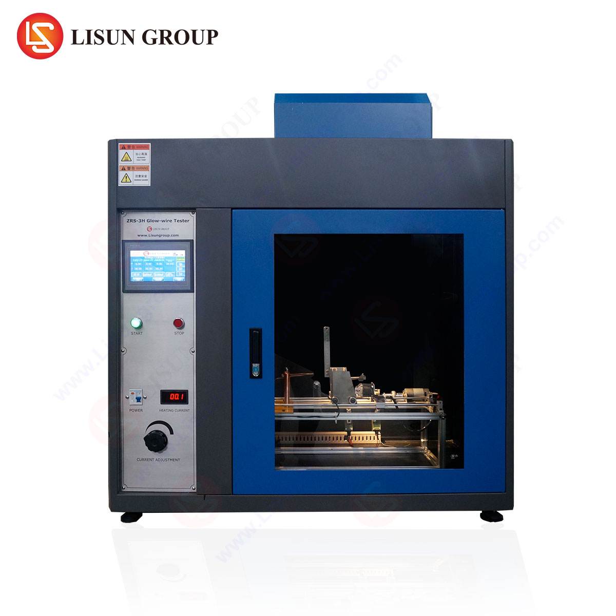
The LISUN ZRS-3H Glow-wire Test Apparatus embodies the technical requirements specified in IEC 60695-2-10, IEC 60695-2-11, IEC 60695-2-12, and IEC 60695-2-13, providing a comprehensive solution for conducting these critical evaluations. Its operational framework is built upon several key subsystems that work in concert to ensure precision and repeatability.
The temperature control system is paramount. The ZRS-3H utilizes a high-precision digital controller coupled with a type K (chromel-alumel) thermocouple to regulate the glow-wire temperature. The thermocouple is spot-welded directly to the surface of the glow-wire, just behind the tip, allowing for direct and instantaneous feedback to the PID (Proportional-Integral-Derivative) controller. This closed-loop system continuously adjusts the current supplied to the glow-wire, compensating for heat dissipation into the test specimen and the surrounding environment to maintain the setpoint temperature with high fidelity.
The mechanical application system ensures consistent and reproducible force application. A mechanism, often pneumatic or solenoid-driven, brings the heated glow-wire into contact with the test specimen with a defined force of 1.0 N ± 0.2 N. This controlled application is critical; excessive force can cause premature deformation and penetration of the specimen, while insufficient force may not provide adequate thermal coupling, both of which would invalidate the test. The apparatus includes a calibrated weight system or a force gauge to verify this parameter.
Furthermore, the ZRS-3H incorporates critical safety and data acquisition features. An enclosure with a transparent, heat-resistant viewport protects the operator from potential spattering or flames. A specimen support and a standardized baize-covered pinewood board are positioned beneath the test piece to assess the propensity for ignited parts or flaming drops to propagate fire. Timing is automatically initiated upon contact, and the apparatus can be equipped with optional flame detection sensors to automatically record the duration of any flames.
Critical Parameters and Failure Criteria in Test Reporting
A Glow Wire Test Report is more than a pass/fail certificate; it is a detailed forensic account of the material’s behavior under thermal stress. The analysis of this report hinges on specific observational parameters and timing data recorded during the test.
The primary failure criteria are:
- Ignition and Sustained Flaming: The specimen must not ignite for longer than 30 seconds after the removal of the glow-wire. Flaming combustion persisting beyond this threshold constitutes a failure. The report must document the duration of any flames (tf).
- Spread of Flame and Ignition of Surroundings: The test is failed if flames or burning particles from the specimen ignite the tissue-paper wrapped pinewood board placed 200 mm below the specimen. This assesses the risk of the product setting fire to its environment.
- Excessive Deformation and Glowing: While not always a direct failure, significant deformation that would compromise the product’s safety or functionality is noted. In some specific tests, the persistence of the specimen’s glow after the removal of the glow-wire is a measured parameter.
A comprehensive report will detail the glow-wire temperature, the applied force, the duration of any flames, whether flaming drops were observed, and the state of the pinewood board. Photographic evidence of the specimen post-test is invaluable for understanding the failure mode, such as the extent of charring, melting, or hole formation.
Industry-Specific Applications and Compliance Imperatives
The application of glow-wire testing is mandated across a vast spectrum of industries, each with its unique risk profile and compliance requirements.
- Household Appliances and Consumer Electronics: Products like electric kettles, hair dryers, televisions, and chargers are tested to ensure that internal faults in motor controllers, power supplies, or connection points do not lead to the ignition of their plastic enclosures. Standards such as IEC 60335-1 specify glow-wire requirements for these products.
- Automotive Electronics: With the increasing electrification of vehicles, components like battery management systems, infotainment units, and wiring harness connectors are subjected to glow-wire testing per standards like ISO 20653. The confined and high-vibration environment of a vehicle makes fire safety non-negotiable.
- Lighting Fixtures: LED drivers, ballasts, and the plastic housings of luminaires can generate significant heat. Glow-wire testing, as per IEC 60598-1, verifies that these components will not ignite under fault conditions, preventing a light fixture from becoming a fire source.
- Medical Devices and Aerospace Components: In these high-reliability sectors, the consequences of failure are severe. Ventilators, patient monitors, and avionics equipment undergo rigorous testing to ensure that even in the event of an internal electrical fault, the integrity of the device is maintained, and fire is prevented, adhering to stringent regulatory frameworks.
- Electrical Components and Telecommunications: Switches, sockets, circuit breakers, and network routers are all prime candidates for this test. A high-resistance connection within a switch, simulated by the glow-wire, must not cause the switch body to sustain a flame.
Comparative Advantages of the LISUN ZRS-3H in Laboratory Environments
In a competitive landscape, the LISUN ZRS-3H distinguishes itself through a combination of engineering precision, operational reliability, and user-centric design features that directly address the pain points of quality assurance laboratories.
A key advantage lies in its thermal stability and calibration integrity. The direct thermocouple attachment and advanced PID algorithm ensure that the set temperature is maintained consistently throughout the 30-second test duration, a factor not always guaranteed in less sophisticated systems. This directly translates to test result reproducibility, a cornerstone of credible laboratory data.
The apparatus also offers enhanced operational safety and efficiency. The interlocked safety door prevents the test from initiating unless the enclosure is secured, protecting the operator. The automated timing and optional flame detection reduce human error in observation and data recording. Furthermore, the robust construction of the glow-wire holder and the specimen support mechanism minimizes maintenance downtime and ensures long-term alignment, which is critical for applying the 1.0 N force accurately test after test.
For laboratories serving multiple industries, the ZRS-3H’s compliance with a full suite of IEC standards makes it a versatile, single-platform investment. Its ability to seamlessly perform tests on end-products (IEC 60695-2-11), material plaques (IEC 60695-2-12), and for the determination of glow-wire flammability index (GWFI) and glow-wire ignition temperature (GWIT) provides comprehensive testing capability.
Interpreting Material Performance Through GWIT and GWFI Indices
Beyond testing finished products, the glow-wire apparatus is instrumental in characterizing the fundamental fire-resistant properties of materials through two key indices: the Glow-Wire Ignition Temperature (GWIT) and the Glow-Wire Flammability Index (GWFI).
The GWIT is the highest temperature at which a material test specimen, 3.0 mm in thickness, does not ignite when exposed to the glow-wire. It is a measure of a material’s inherent resistance to ignition under this specific thermal insult. A material with a GWIT of 850°C is superior to one with a GWIT of 750°C for a given application.
The GWFI is a more complex metric. It is the highest temperature at which a material specimen does not ignite or, if it does ignite, self-extinguishes within 30 seconds after removal of the glow-wire and does not ignite the tissue paper below. It provides a combined measure of ignition resistance and flame self-extinction. A material must achieve a GWFI equal to or higher than the temperature specified in the end-product standard.
These indices, generated using the LISUN ZRS-3H, allow design engineers to make informed material selection decisions early in the product development cycle, rather than relying on costly and time-consuming end-product testing for each material candidate.
Integrating Glow-Wire Test Data into Product Development and Risk Assessment
The ultimate value of glow-wire testing is realized when its data is proactively integrated into the product design and risk assessment process. A test report should not be viewed in isolation but as a critical input for a Failure Mode and Effects Analysis (FMEA). For instance, if a particular plastic resin used for a power supply housing fails the glow-wire test at 750°C, the design team has several actionable paths: they can source a higher-performance, flame-retardant grade of material, redesign the housing to include thermal barriers or heat sinks to protect the plastic from hot components, or modify the internal layout to increase clearance and creepage distances, thereby reducing the likelihood of a fault occurring in the first place. This iterative process, fueled by precise test data from reliable apparatus, is fundamental to designing inherently safe products that comply with global market access requirements.
Frequently Asked Questions (FAQ)
Q1: What is the primary difference between the Glow-Wire Test and the Needle-Flame Test?
While both assess fire hazard, they simulate different fault conditions. The Glow-Wire Test simulates the effect of a heated or glowing element in poor electrical contact (e.g., an overloaded resistor or a loose terminal). The Needle-Flame Test (IEC 60695-2-2) simulates a small flame that may result from an ignition source within the equipment, applying a small but direct flame to the specimen. The test principles, apparatus, and failure criteria are distinct.
Q2: How often should the LISUN ZRS-3H Glow-wire Test Apparatus be calibrated?
Calibration frequency should be determined by the laboratory’s quality procedures, typically aligned with ISO/IEC 17025. It is generally recommended to perform a full calibration annually. However, critical components like the force application mechanism and the thermocouple should be verified before each testing session or series of tests to ensure ongoing accuracy.
Q3: Can the ZRS-3H be used for testing non-plastic materials, such as composites or thin foils?
Yes, the test standards and the apparatus are applicable to all solid electrotechnical insulating materials, not solely plastics. However, the test setup, including the specimen support, may need to be adapted for non-rigid materials to ensure the standard 1.0 N force is properly applied. The applicable product standard for the end-use should be consulted for any material-specific testing provisions.
Q4: What does a “pass” for GWFI actually mean in practice?
A material that achieves a GWFI of, for example, 850°C, has demonstrated that at that temperature, it will either not ignite, or if it does, any flames will self-extinguish within 30 seconds without setting fire to the surrounding materials (simulated by the tissue paper). This allows engineers to specify that this material is safe for use in applications where the internal components are unlikely to exceed this temperature threshold under fault conditions.
Q5: Why is the force of application (1.0 N ± 0.2 N) so critical to the test’s reproducibility?
The applied force directly affects the thermal contact resistance between the glow-wire tip and the specimen surface. Too little force results in poor heat transfer, potentially leading to a non-ignition result that is not representative of a real fault. Too much force can cause mechanical deformation or penetration of the specimen, altering its thermal properties and potentially causing an ignition that is an artifact of the test setup, not the material’s performance. Strict control of this parameter is essential for inter-laboratory reproducibility.