


Evaluating Fire Hazard Resistance: The Role of Glow Wire Testing in Product Safety Compliance
The imperative to mitigate fire risks in electrically energized components and enclosures is a foundational principle across global manufacturing sectors. As materials science advances and product designs become increasingly compact and complex, traditional flammability tests may not adequately simulate real-world fault conditions involving thermally stressed components. The glow wire test, a rigorous and standardized assessment method, addresses this gap by evaluating a material or assembly’s resistance to ignition and its ability to limit flame propagation when exposed to a heated element. This technical analysis examines the principles, applications, and critical importance of glow wire testing, with a detailed focus on the implementation provided by modern instrumentation such as the LISUN ZY-3 Needle Flame Tester.
Fundamental Principles of the Glow Wire Test Simulation
The core objective of the glow wire test is to replicate a thermal stress scenario that might occur in service due to overloaded, poorly connected, or failing electrical parts. Unlike flame application tests that assess direct flammability, this method employs a electrically heated wire or rod—the glow wire—maintained at a precisely controlled temperature. This element is then brought into contact with the test specimen under a defined force for a specified duration. The test does not merely assess if a material ignites; it provides a comprehensive evaluation of behavioral characteristics during and after the thermal insult.
The assessment parameters are multifaceted. Observers document whether the specimen ignites and, if so, the duration of any flames (flame persistence time) and whether glowing or flaming particles drip from the specimen. The propensity for these particles to ignite a tissue paper substrate positioned below is a critical pass/fail criterion, as it directly correlates to the risk of secondary fire ignition. The test’s scientific validity stems from its simulation of a localized, high-temperature point source, a common precursor to catastrophic failure in insulating materials, connector housings, and PCB substrates.
Regulatory Framework and Standardization Mandates
Glow wire testing is not a discretionary quality check but a mandated compliance requirement embedded within international safety standards. Its primary governance derives from the IEC 60695-2 series, specifically standards such as IEC 60695-2-10, -11, -12, and -13, which detail the test apparatus, calibration procedures, and severity levels. These standards are harmonized into numerous national and regional regulations, including the European EN 60695-2 series and Underwriters Laboratories (UL) standards like UL 746A.
The severity of the test is dictated by the Glow Wire Ignition Temperature (GWIT) and the Glow Wire Flammability Index (GWFI). The GWIT is the temperature 25°C above the maximum test temperature at which the material does not ignite, or ignites for less than 5 seconds. The GWFI is the highest temperature at which a material does not ignite for longer than 30 seconds, and no dripping particles ignite the tissue paper. Compliance thresholds are explicitly defined in end-product standards. For instance, IEC 60335-1 for household appliances, IEC 60950-1 for IT equipment (superseded but illustrative), and IEC 60601-1 for medical electrical equipment all incorporate glow wire requirements for enclosures and parts supporting current-carrying components. The automotive sector references similar protocols in various ISO and OEM-specific specifications for passenger compartment and under-hood electronics.
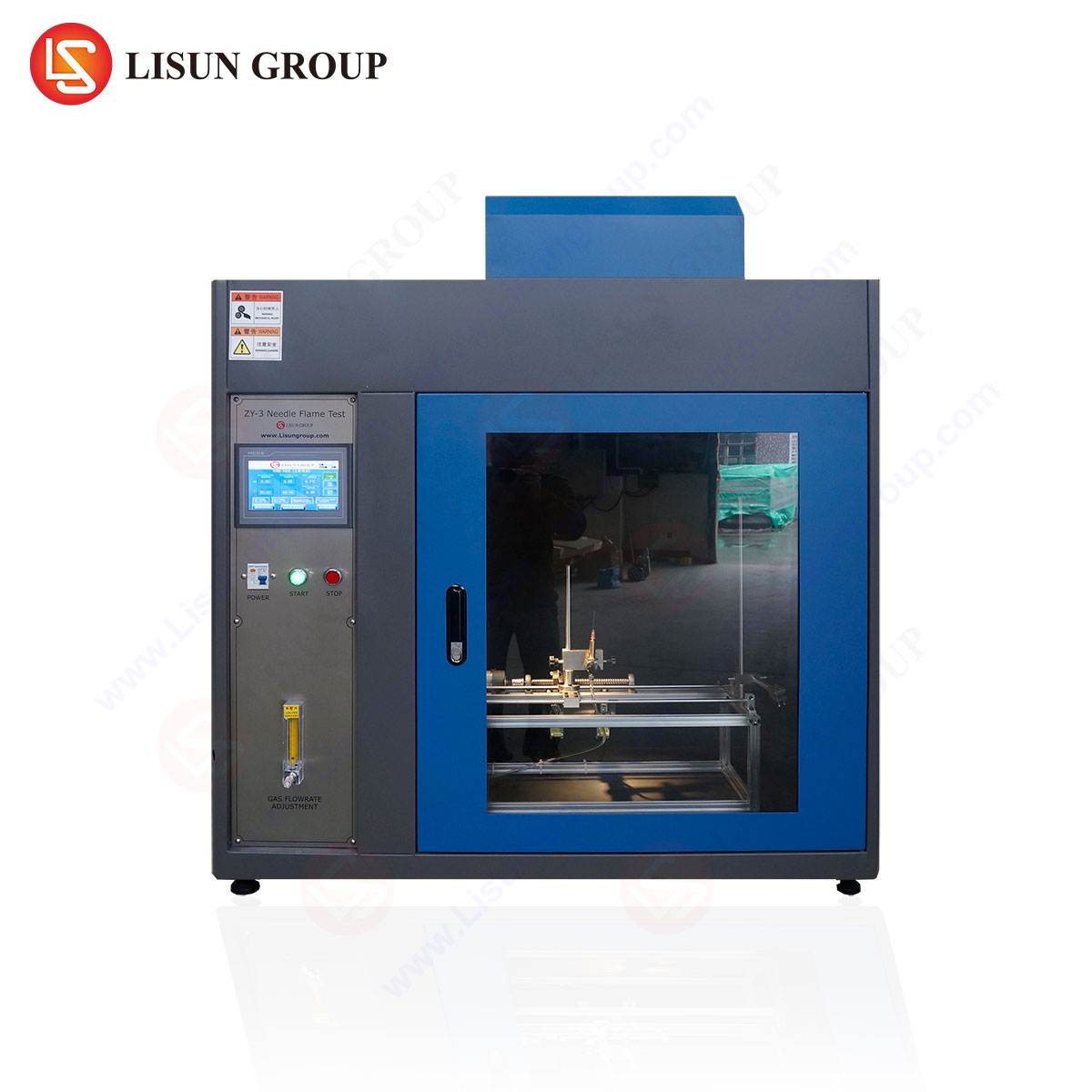
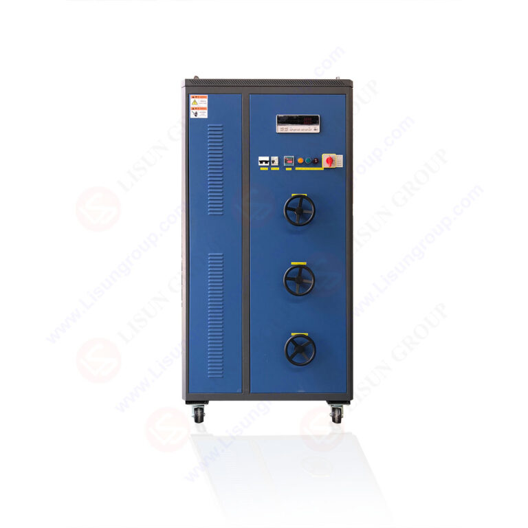
The LISUN ZY-3 Needle Flame Test Apparatus: System Architecture and Operational Fidelity
Implementing the standardized test methodology demands instrumentation of high precision, repeatability, and safety. The LISUN ZY-3 Needle Flame Test apparatus is engineered to meet the exacting specifications of IEC 60695-2-2, which governs the needle flame test—a related but distinct small flame ignition test—and is constructed to principles applicable for rigorous thermal testing. Its design facilitates accurate simulation of fault conditions from small flames or heated elements.
The system’s architecture is built around several key subsystems:
- Thermal Element and Precision Heating Control: A high-resistance alloy glow wire (or a specified burner for needle flame tests) is heated by a stabilized power supply. A closed-loop PID temperature control system, coupled with a calibrated Type K thermocouple, ensures the test element reaches and maintains the target temperature (±2°C tolerance) as stipulated by the standard, typically ranging from 550°C to 960°C.
- Automated Application Mechanism: A servo-driven or pneumatic application system advances the heated element to the specimen with a repeatable force (typically 1.0 N ± 0.2 N) and contact duration (30 seconds ± 1 second). This automation eliminates operator variability, a critical factor in achieving reproducible results.
- Integrated Safety and Fume Extraction: A transparent, interlocked safety enclosure protects the operator. An integrated fume extraction system, with adjustable flow rate, removes pyrolysis and combustion products, maintaining laboratory air quality and ensuring clear observation.
- Calibration and Validation Suite: The apparatus includes dedicated calibration tools, such as a silver foil temperature verification kit, to periodically confirm the thermal accuracy of the glow wire, as mandated by IEC 60695-2-10.
Table 1: Representative Technical Specifications of the LISUN ZY-3 System
| Parameter | Specification |
| :— | :— |
| Temperature Range | 100°C to 1000°C (continuously adjustable) |
| Temperature Stability | ±2°C at set point |
| Test Duration Timer | 0 to 999.9 seconds, digital display |
| Application Force | 1.0 N ± 0.2 N (adjustable) |
| Specimen Mounting | Multi-axis adjustable clamp and holder |
| Safety Enclosure | Transparent, mechanically interlocked |
| Compliance Standards | IEC 60695-2-2, GB/T 5169.5, et al. |
Cross-Industry Application Scenarios for Hazard Assessment
The utility of glow wire testing spans industries where electrical and electronic components are housed in potentially combustible materials or where their failure could instigate a fire.
- Household Appliances & Consumer Electronics: Control panels, switch housings, connector blocks, and internal supports in devices like washing machines, air conditioners, and televisions are tested to ensure a faulty thermostat or overloaded connection does not cause the enclosure to ignite.
- Automotive Electronics: Components within the passenger compartment (e.g., infotainment systems, switchgear, wiring harness clips) and under-hood modules (engine control unit housings) are evaluated for resistance to thermal exposure from short circuits.
- Lighting Fixtures: Lampholders, LED driver housings, and diffuser materials are subjected to testing, as high-wattage LEDs or ballasts can generate significant localized heat.
- Medical Devices & Aerospace Components: For patient-connected monitors and critical avionics, the test verifies that material failures do not create an ignition source in oxygen-enriched or confined, critical environments.
- Industrial Control & Telecommunications: PLC housings, terminal blocks, server rack components, and router enclosures in unattended or high-reliability installations must prevent fault propagation.
- Electrical Components & Wiring Systems: Switches, sockets, circuit breaker casings, and cable insulation sleeves are prime candidates for this evaluation.
Methodological Execution and Data Interpretation
A standardized test procedure is critical. The specimen, conditioned to a standard atmosphere, is mounted securely. The glow wire is heated to the severity temperature specified by the applicable end-product standard (e.g., 750°C for parts in household appliances requiring fire enclosure resistance). After thermal stabilization, it is applied to the specimen. Post-application, observations are meticulously recorded: time to ignition (if any), duration of flames after removal of the glow wire, and whether burning or glowing drips occur. The test is repeated on multiple specimens to ensure statistical validity.
Interpretation goes beyond a binary pass/fail. A material that exhibits brief ignition (<2 seconds) with no dripping presents a markedly lower hazard profile than one that sustains flames for 15 seconds and produces igniting droplets. The former may be acceptable in certain applications, while the latter would necessitate material reformulation or protective redesign. The data directly informs material selection, component geometry (e.g., adding flame barriers or drip shields), and ultimately, the product’s safety certification.
Comparative Advantages of Automated Testing Instrumentation
Utilizing a dedicated, automated system like the LISUN ZY-3 confers significant advantages over ad-hoc or manual test setups. Primarily, it ensures standard compliance and auditability. The precision in temperature control, application force, and timing meets the normative references exactly, generating defensible data for certification bodies like TÜV, UL, or Intertek. Secondly, it delivers high repeatability and reproducibility (R&R), minimizing inter-operator and inter-laboratory variability, which is a common challenge in subjective fire testing. Thirdly, enhanced operator safety is achieved through full enclosure, interlocking, and fume extraction. Finally, improved testing efficiency through automated sequences and digital logging accelerates the product development and qualification cycle.
Integrating Glow Wire Data into Product Development and Risk Management
Proactive manufacturers integrate glow wire testing not as a final compliance hurdle, but as an integral component of the Design for Safety (DfS) and risk management process, per ISO 14971. Early-stage screening of material candidates using GWIT and GWFI data prevents costly redesigns later. The test results feed directly into the product’s hazard analysis, informing decisions on component spacing, use of metallic heat sinks, ventilation design, and the inclusion of flame-retardant compounds. In essence, it transforms a compliance activity into a critical engineering input for enhancing product reliability and safety integrity.
Frequently Asked Questions (FAQ)
Q1: What is the key difference between the Glow Wire Test and the Needle Flame Test?
The Glow Wire Test (IEC 60695-2-1x) uses an electrically heated solid element to simulate heat from an overloaded or glowing component. The Needle Flame Test (IEC 60695-2-2) uses a small, defined gas flame to simulate the effect of a small ignition source, like a fault-induced arc, on a product. Both assess fire hazard but simulate different physical fault conditions.
Q2: How often should the temperature calibration of the glow wire apparatus be performed?
Calibration frequency should follow the laboratory’s quality procedure, typically aligned with ISO/IEC 17025 guidelines. It is generally recommended before a major test series, after replacing the glow wire, and at regular intervals not exceeding 12 months. A routine check using a reference material or silver foil validation before each day’s testing is considered best practice.
Q3: Can the LISUN ZY-3 be used for testing non-planar or irregularly shaped components?
Yes. A critical feature of compliant apparatus is a versatile specimen mounting system. The ZY-3 includes adjustable clamps and holders that can secure a variety of geometries—from flat plaques to curved housings or actual sub-assemblies—ensuring the test element can be applied to the required location as specified in the end-product standard.
Q4: What factors most commonly lead to a failed glow wire test result?
Failure typically stems from material selection. Thermoplastics with low thermal stability or without appropriate flame-retardant additives will ignite readily and sustain combustion. Design also plays a role: thin wall sections heat through more quickly, and geometries that pool molten material can promote dripping. The solution often involves upgrading to a material with a higher GWFI/GWIT rating or adding protective metallic shields.
Q5: Is glow wire testing required for all plastic parts in an electronic device?
No. The requirement is risk-based. Standards typically mandate testing for parts that provide fire enclosure (external housings) and for parts supporting current-carrying components that could become faulty (e.g., socket bases, relay housings). Internal plastic parts with no safety function and located far from electrical parts may be exempt. The applicable end-product standard provides the definitive scope.