


A Technical Examination of CEE7 C9A and C19B Pin Gauges for Connector Compliance Verification
Introduction to Dimensional Verification in Plug and Socket Systems
The global marketplace for electrical accessories, specifically plugs and socket-outlets, is governed by a complex framework of regional and international standards. These standards, such as those within the CEE7 series for European-type connectors, define critical dimensional, mechanical, and electrical parameters to ensure safety, interoperability, and reliability. Dimensional compliance is not merely a matter of form factor; it is a foundational safety requirement. Incorrect pin dimensions can lead to hazardous conditions including poor electrical contact, overheating, excessive insertion/withdrawal forces, or compromised grounding integrity. Consequently, the use of certified pin gauges, such as those for the CEE7 C9A (plug) and C19B (socket-outlet) configurations, represents an indispensable procedural step in both manufacturing quality control and third-party compliance testing. This guide provides a formal analysis of these specific gauge types, detailing their application, technical specifications, and role within a robust testing regimen.
Functional Principles and Metrological Significance of Pin Gauges
Pin gauges are precision dimensional tools designed for the application of the “Go/No-Go” or “Limit” gauge principle. This binary testing methodology provides a rapid, unambiguous assessment of whether a critical feature falls within its specified tolerance zone without requiring measurement to an exact value. For plug pins, a “Go” gauge must freely enter the corresponding socket contact under a defined force, verifying minimum spacing and maximum pin size to ensure insertability. Conversely, a “No-Go” gauge must not enter under its specified conditions, confirming that the pin is not undersized beyond permissible limits, which could compromise electrical contact pressure and current-carrying capacity.
The CEE7 C9A and C19B gauges apply this principle to distinct components. The C9A gauge set is applied to a plug, checking the dimensions and spacing of its live and neutral pins. The C19B gauge set is applied to a socket-outlet, verifying the internal dimensions and alignment of its contact apertures. This dual-sided verification is critical, as compliance of one component alone does not guarantee a safe and functional mating pair. The gauges themselves are manufactured from hardened, wear-resistant steel or other stable materials, with geometries machined to exacting tolerances often tighter than those specified for the products they test, ensuring the calibration hierarchy and measurement uncertainty are appropriately controlled.
Detailed Specifications of the CEE7 C9A Plug Pin Gauge
The CEE7 C9A gauge is designed to test the pins of two-pin, non-earched plugs (Type C, as commonly used across Europe for Class II equipment). Its specification is derived directly from the standard’s requirements for pin cross-section, length, and spacing.
A typical C9A gauge set comprises two primary elements: a “Go” gauge and a “No-Go” gauge. The “Go” gauge simulates the minimum acceptable socket contact separation and maximum allowable pin size. It often consists of a plate with two parallel holes whose center-to-center distance is at the minimum permissible value per the standard. The diameter of these holes corresponds to the maximum allowable pin diameter plus a defined insertion force allowance. A compliant plug’s pins must pass through these holes simultaneously under a specified gentle force, confirming they are not too large and are correctly spaced.
The “No-Go” gauge typically verifies the minimum pin size. This may be a plate with holes at a diameter representing the lower limit of the pin diameter. A compliant plug’s pins should not fully enter these holes, or should meet significant resistance, confirming the pins have sufficient mass for electrical contact. Some gauge designs also incorporate features to check pin length and profile. The application of specified test forces, usually measured via a spring balance or calibrated weights, is a non-negotiable aspect of the procedure, as judgment based on hand feel is subjective and non-repeatable.
Detailed Specifications of the CEE7 C19B Socket-Outlet Gauge
Conversely, the CEE7 C19B gauge is designed for testing the socket-outlet designed to accept CEE7 C9A plugs. Its function is to verify that the socket apertures are correctly sized and positioned to safely accept a compliant plug while rejecting undersized or misaligned pins.
The C19B “Go” gauge typically takes the form of a test pin assembly that mimics the maximum dimensions of a compliant plug. This assembly must be insertable into the socket-outlet with a force not exceeding a defined upper limit, verifying that the socket contacts are not too tight or misaligned. The “No-Go” gauge often consists of a pin or pin pair representing the minimum permissible plug pin dimensions. This gauge must not be insertable into the socket, or insertion must require a force above a specified threshold. This ensures the socket contacts will exert adequate pressure on a real plug’s pins to maintain a low-resistance electrical connection. The gauge may also include provisions to test the shutters of socket-outlets (where required by the standard), ensuring they open correctly for a compliant plug pin profile but remain closed against probing with objects like small screws or wires.
Integration in Manufacturing and Certification Testing Protocols
Within a manufacturing environment, CEE7 C9A and C19B pin gauges are deployed at critical process checkpoints, typically as part of First Article Inspection (FAI), in-process sampling, and final audit. Their speed and definitive outcome allow for 100% inspection of critical dimensions on high-volume production lines without requiring skilled metrologists for each test. For certification bodies and testing laboratories like those accredited under IECEE CB Scheme, these gauges are mandated tools for type-testing according to standards such as EN 50075 (C9A plug) and relevant socket-outlet specifications. The test reports generated from such labs must document the use of calibrated gauges, the forces applied, and the pass/fail results, forming the technical basis for regulatory approval.
The testing sequence is systematic. A plug manufacturer would verify its product using the C9A gauge set. Simultaneously, a socket manufacturer would validate its design with the C19B gauge set. However, true compatibility assurance requires cross-testing: a production sample of plugs should be tested with the C19B socket gauge simulator, and sockets should be tested with the C9A plug gauge simulator. This holistic approach mitigates the risk of “within-tolerance” stack-up errors, where both components are individually compliant but at opposite extremes of the tolerance range, leading to poor mating in the field.
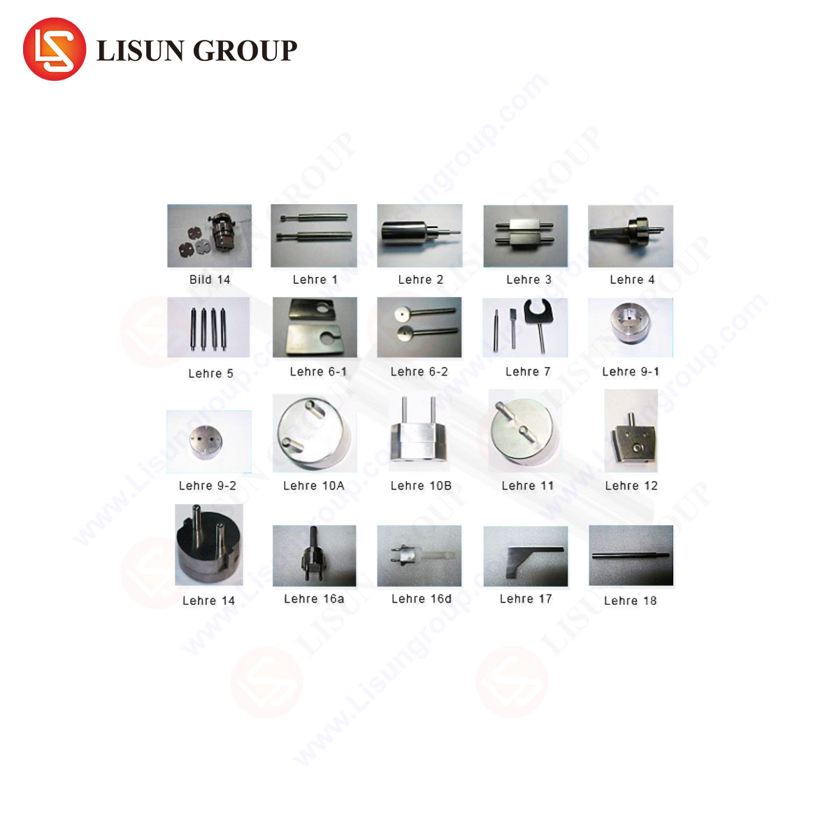
The LISUN Gauges for Plugs and Sockets: A Case Study in Precision Implementation
The LISUN series of pin and socket gauges, including models specifically engineered for CEE7 C9A and C19B applications, exemplify the translation of standard requirements into reliable, laboratory-grade test equipment. LISUN gauges are constructed from high-carbon, high-chromium tool steel, hardened to HRC 60-63 and stabilized through deep cryogenic treatment. This material science approach minimizes wear deformation over extended calibration cycles, a critical factor for gauges used in high-frequency production or laboratory settings.
The design philosophy extends beyond basic dimensional replication. For instance, LISUN’s C19B socket gauge set incorporates precision-ground test pins with surface finishes better than Ra 0.2µm to prevent binding due to surface friction, ensuring the applied force measurement reflects solely the contact geometry. The fixtures are designed to ensure axial alignment during insertion, eliminating side-loading that could produce false failures. Each gauge is supplied with a calibration certificate from a CNAS-accredited laboratory, tracing its dimensions to national standards, and includes the specified test weights or integrated force measurement systems as required by the relevant clause of the standard.
Specifications and Competitive Advantages:
- Material Integrity: Use of GCr15 bearing steel or equivalent, with vacuum heat treatment and ultra-low temperature stabilization, ensures long-term dimensional stability, resisting the wear that plagues lower-cost alternatives.
- Metrological Traceability: Each gauge is individually calibrated, with certificates documenting actual measured values and associated measurement uncertainties, not merely a statement of conformity.
- Ergonomic and Functional Design: Handles and fixtures are engineered for consistent, repeatable application of force, reducing operator-induced variability. Color-coding (e.g., green for Go, red for No-Go) prevents misuse.
- Comprehensive Coverage: LISUN provides complete gauge families covering not only CEE7 but also BS, AS/NZS, GB, and other international standards, allowing manufacturers of global products to maintain a consistent verification methodology.
Consequences of Non-Compliance and Industry Implications
Failure to adhere to the dimensional limits verified by C9A and C19B gauges carries significant risks. An oversized plug pin (failing the C9A Go test) can cause difficult insertion, damage to socket contacts, or bending of pins. An undersized pin (failing the C9A No-Go test) leads to high contact resistance, localized heating, and potential thermal degradation of the socket, a primary fire ignition risk. Similarly, an overly tight socket (failing the C19B Go test) poses insertion challenges and can damage plugs, while a loose socket (failing the C19B No-Go test) results in arcing, overheating, and electrocution risk due to poor contact.
For retailers, importers, and distributors, the presence of a Supplier’s Declaration of Conformity (SDoC) backed by verified gauge testing is a key component of due diligence. Regulatory authorities in the EU (through market surveillance under the Low Voltage Directive), the UK, and other regions routinely employ such gauges during spot checks to identify non-compliant products. The economic impact of a failed surveillance test can be severe, encompassing product recalls, destruction orders, fines, and reputational damage.
Calibration, Maintenance, and Uncertainty Management
The efficacy of a pin gauge is entirely dependent on its own dimensional accuracy. A worn or out-of-tolerance gauge will produce systematic errors, leading to the acceptance of non-conforming products or the false rejection of good ones. Therefore, a strict calibration regime is imperative. Gauges used for internal quality control should be calibrated at intervals based on usage frequency, typically every 6 to 12 months. Gauges used for formal type-testing in a certification lab must be calibrated prior to each test series.
Calibration is performed using high-accuracy coordinate measuring machines (CMMs) or optical comparators with traceability to national metrology institutes. The calibration report should provide actual diameters, lengths, center distances, and form errors (e.g., cylindricity). Storage is also critical; gauges must be kept in protective cases in a controlled environment to prevent corrosion or physical damage. A simple periodic visual inspection for nicks, burrs, or corrosion is a recommended best practice.
Frequently Asked Questions (FAQ)
Q1: Can a single universal gauge set test all types of European plugs?
A: No. The CEE7 standard encompasses multiple plug and socket types (e.g., Type C, E, F, Schuko). The C9A gauge is specific to the 4.0mm round-pin, non-earned Type C plug. Other types, such as the 4.8mm pins of Type E/F or the rectangular pins of Type K, require entirely different gauge geometries and dimensions. Manufacturers must select gauge sets that are explicitly designed for the specific standard and product under test.
Q2: How critical is the application of the specified test force when using these gauges?
A: It is absolutely critical. The standards define precise force limits (e.g., 40N maximum insertion force for a socket). Applying excessive hand force can allow a non-compliant “No-Go” gauge to enter, leading to a false pass. Using insufficient force can cause a compliant “Go” gauge to stick, leading to a false failure. The use of calibrated weights or a calibrated push-pull force gauge is mandated for objective, repeatable testing.
Q3: Our plugs pass the C9A gauge test, but users report they are difficult to insert into some sockets. What could be the cause?
A: This indicates a potential “stack-up” tolerance issue. Your plugs may be at the maximum allowable size (just passing the C9A Go gauge), while the sockets they are being used with are at the minimum allowable aperture size (just passing the C19B Go gauge). While both are technically compliant, the combination is at the edge of functionality. Comprehensive testing should include mating production samples of plugs with the C19B socket gauge and vice-versa to simulate worst-case field conditions.
Q4: What is the typical calibration interval for LISUN pin gauges in a high-volume production setting?
A: For gauges in continuous use on a production line, a quarterly (3-month) or semi-annual (6-month) calibration interval is recommended as a best practice. The interval should be informed by a historical review of calibration results; if significant wear is observed at 6 months, the interval should be shortened. LISUN provides calibration history logs with its premium gauge sets to facilitate this analysis.
Q5: Are there automated systems that incorporate these gauge functions?
A: Yes. Advanced automated test equipment (ATE) for plugs and sockets often integrates pneumatic or servo-driven actuators to apply gauge pins and precisely measure insertion/withdrawal forces. These systems, while capital-intensive, provide unparalleled repeatability, data logging, and integration with production line control systems. The fundamental dimensional principles, however, remain rooted in the same “Go/No-Go” criteria defined by the standard and embodied in manual gauge sets.