


A Technical Analysis of High-Current Electrical Safety Probes for Connector Integrity Verification
Introduction: The Critical Role of Connector Testing in Electrical Safety
Within the infrastructure of electrical power distribution and utilization, the humble plug and socket interface represents a critical point of potential failure. These connectors are subjected to repeated mechanical stress, thermal cycling, and environmental exposure, which can degrade their current-carrying capacity and insulation integrity over time. A compromised connection, particularly in high-current applications, can lead to catastrophic outcomes including localized overheating, insulation breakdown, fire initiation, and equipment damage. Consequently, the non-destructive evaluation of plug and socket assemblies is not merely a maintenance procedure but a fundamental component of proactive electrical safety protocols. This article examines the design, operational principles, and application of specialized High-Current Electrical Safety Probes, with a specific focus on their implementation for verifying the safety and performance of plugs and sockets in accordance with international standards.
Defining the High-Current Electrical Safety Probe: Operational Parameters and Design Philosophy
A High-Current Electrical Safety Probe is a precision instrument engineered to apply a controlled, elevated current through an electrical connector for a defined duration while simultaneously monitoring key parameters. Its primary function is to simulate operational or fault conditions to assess the connector’s ability to handle its rated current without excessive temperature rise or voltage drop. Unlike standard continuity testers, these probes are designed to deliver currents ranging from tens to several hundred amperes, commensurate with the ratings of industrial and high-power commercial connectors.
The core design philosophy integrates three essential subsystems: a high-current regulated power source capable of maintaining stable output under variable load impedance; a precision measurement module for real-time acquisition of current, voltage at the point of load, and temperature; and a robust, application-specific probe tip assembly that ensures low-contact-resistance mating with the device under test (DUT). The probe tip is often a critical, custom-designed component, fabricated from materials with high electrical conductivity and thermal stability, such as beryllium copper or specially plated alloys, to prevent the probe itself from becoming a significant heat source or voltage drop contributor during the test.
Quantifying Connector Degradation: The Principles of Temperature-Rise and Contact-Resistance Testing
The fundamental testing principle hinges on the relationship between electrical resistance, current flow, and thermal energy dissipation, as defined by Joule’s Law (P = I²R). In a pristine connector, the contact resistance between mating conductive parts is exceptionally low. However, factors such as contact surface oxidation, fretting corrosion, loss of contact spring force, or physical deformation can cause this resistance to increase incrementally. Under high current, this elevated resistance results in localized power dissipation, manifesting as a temperature rise at the contact point.
A High-Current Safety Probe operationalizes this principle by performing a Temperature-Rise Test. The probe applies the connector’s rated current (or a specified test current per relevant standards like IEC 60884-1 or UL 498) for a standardized period. Infrared thermography or embedded thermocouples in the probe assembly measure the temperature increase of the connector’s pins, sleeves, or surrounding housing. This measured ΔT (temperature rise) is compared against maximum permissible limits outlined in safety standards, typically ranging from 30°K to 50°K depending on the connector type and material. An excessive temperature rise indicates degraded contacts, insufficient contact pressure, or undersized conductors, flagging the connector as a safety hazard.
Complementarily, the Contact Voltage-Drop Test provides a direct electrical measurement of contact quality. While applying the high test current, the probe utilizes a separate, high-impedance sensing circuit to measure the millivolt-level potential difference directly across the mated contacts (excluding the voltage drop in the connected wires). This measured voltage drop, when divided by the applied current, yields the dynamic contact resistance. A rising trend in contact resistance over successive test cycles or a value exceeding manufacturer or standard specifications provides a quantifiable metric of connector wear and impending failure.
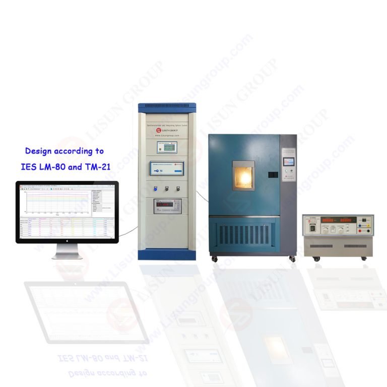
LISUN Gauges for Plugs and Sockets: A Specialized Implementation for Standardized Testing
A prominent example of a dedicated system in this domain is the LISUN series of gauges and test apparatus for plugs and sockets. These instruments are engineered to provide a comprehensive, standards-compliant assessment of connector safety. The LISUN system typically incorporates a high-current probe apparatus designed to interface precisely with standardized socket geometries and plug pins.
The testing procedure involves inserting the calibrated probe pins into the socket outlets or attaching the probe to plug pins. The system then automatically sequences through a test regimen that may include:
- Rated Current Temperature Rise Test: Applying the socket’s nominal current (e.g., 16A, 32A) and measuring pin temperature.
- Normal Operation Test: Simulating repeated insertion and withdrawal cycles under load.
- Durability of Terminals Test: Assessing the integrity of screw terminals or other connection methods within the socket after thermal stress.
Key specifications for such a system, exemplified by LISUN’s offerings, include:
- Current Output Range: 0 – 200A (or higher), programmable and stable.
- Temperature Measurement: Integrated K-type thermocouples with an accuracy of ±1.5°C, positioned at critical points.
- Voltage Drop Measurement: Resolution to 0.1 mV across the contact interface.
- Compliance: Direct alignment with test clauses from IEC 60884-1, GB 2099.1, and other national derivatives for plugs and socket-outlets for household and similar purposes.
- Control & Data Acquisition: Automated test sequencing, real-time data logging, and generation of pass/fail reports based on configurable thresholds.
The competitive advantage of such an integrated system lies in its reproducibility and standardization. By using geometrically precise probe pins and automated control, it eliminates operator variability, ensuring that test results are solely indicative of the DUT’s condition and not influenced by inconsistent probe contact. This is crucial for both manufacturer quality control and third-party certification testing.
Industry Applications: From Manufacturing QC to Predictive Maintenance
The application of High-Current Safety Probes spans the entire lifecycle of electrical connectors.
-
Manufacturing Quality Assurance: In production lines for plugs, sockets, and appliance inlets/couplers, 100% testing or statistical batch testing is mandated. Probes verify that every unit meets the temperature-rise limits before leaving the factory. This catches defects like poorly plated contacts, faulty terminal screws, or substandard contact springs.
-
Certification Laboratory Testing: Third-party testing laboratories (e.g., UL, TÜV, Intertek) utilize these probes as part of type-testing for safety certification. They rigorously apply stress tests, including prolonged high-current exposure, to validate a product design’s compliance before it is allowed on the market.
-
Field-Based Predictive Maintenance: For critical infrastructure—data centers, industrial manufacturing plants, hospital power systems—periodic testing of installed socket outlets and connectorized power distribution units (PDUs) is essential. Portable high-current probe kits allow facility engineers to survey installed bases, identifying sockets that have degraded due to age, corrosive environments, or mechanical wear from frequent use. Replacing a socket showing a 45°K temperature rise during a 16A test is a proactive measure that prevents a potential fire ignition point.
-
Investigation of Field Failures: When a failure occurs, such as a melted socket, safety probes can be used to test adjacent, seemingly unaffected outlets on the same circuit to determine if the failure was an isolated incident or indicative of a systemic issue with the installed product batch or environmental conditions.
Integrating Test Data into a Comprehensive Safety Management Framework
The data generated by High-Current Safety Probes is not merely a pass/fail datum. When logged over time, it forms a vital part of a Condition-Based Maintenance (CBM) strategy. Trending the contact resistance or temperature rise of specific sockets over annual inspections can predict end-of-life, allowing for planned, non-emergency replacements. This data can be integrated into computerized maintenance management systems (CMMS) to build a historical performance profile of electrical assets.
Furthermore, the objective evidence provided by these tests is invaluable for compliance with workplace safety regulations (e.g., OSHA, NFPA 70E), which require employers to maintain electrical equipment in a safe operating condition. A documented testing protocol using calibrated, fit-for-purpose equipment demonstrates due diligence.
Conclusion
The High-Current Electrical Safety Probe represents a sophisticated convergence of electrical engineering, thermal analysis, and precision measurement. By moving beyond simple continuity checks to dynamic, quantitative assessment under realistic load conditions, these instruments provide an unambiguous evaluation of the most fundamental component in electrical safety: a sound connection. As exemplified by dedicated systems like the LISUN gauges for plugs and sockets, the standardization and automation of these tests ensure reliable, repeatable safety verification across global manufacturing and maintenance practices. In an era increasingly dependent on reliable electrical power, such tools are indispensable for mitigating risk, ensuring compliance, and safeguarding both property and personnel from the hazards of connector failure.
FAQ
Q1: How often should installed socket outlets be tested with a high-current probe in a commercial facility?
Testing frequency should be risk-based. For critical environments like data centers or industrial floors, an annual or biennial thermographic survey supplemented by spot-check high-current testing of representative samples is recommended. Following any electrical incident, or in harsh environments (high humidity, corrosive atmospheres), more frequent testing is advised. Always consult the equipment manufacturer’s guidelines and relevant national electrical safety codes.
Q2: Can a standard clamp meter or low-current multimeter substitute for a dedicated high-current safety probe?
No. Standard clamp meters measure current in a conductor but cannot apply a controlled load or measure the critical voltage drop directly across the mated contacts. Low-current resistance measurements (e.g., using a DMM) are ineffective as they do not overcome the oxide films on contact surfaces; only a high test current can break down these micro-films and reveal the true dynamic contact resistance under operational conditions.
Q3: What are the primary safety precautions when operating a high-current probe?
Operators must be qualified for working on energized equipment. Precautions include: wearing appropriate personal protective equipment (PPE) for arc flash hazards; ensuring the DUT is isolated from mains supply and only energized by the test equipment; verifying the probe and test leads are rated for the intended current and duration; and being aware that connector housings can become extremely hot during testing.
Q4: For a LISUN-type gauge system, how is the temperature measurement calibrated to ensure accuracy?
The integrated thermocouples are calibrated against a traceable standard using a dry-block calibrator or precision temperature bath. The entire measurement channel—thermocouple, compensation wire, and instrument input—should be validated periodically. The system software often includes routines for offset calibration at known reference points (e.g., 0°C in an ice bath).
Q5: Do high-current tests damage or accelerate the wear of a functional connector?
When performed according to standard durations (typically 1 hour for temperature-rise tests), the test is designed to be non-destructive for a compliant connector. It applies stress equivalent to normal operational extremes. However, repeated testing beyond standard requirements could contribute to contact wear. The test is intended as a verification of inherent safety, not an endurance trial.