


The Critical Role of High Temperature Test Equipment in Modern Product Validation
The relentless pursuit of product reliability, safety, and longevity across industrial sectors necessitates rigorous environmental simulation. Among these simulations, high temperature testing stands as a fundamental pillar, exposing materials and assemblies to thermal stresses that reveal latent defects, validate design limits, and ensure operational integrity under extreme conditions. High temperature test equipment, therefore, is not merely a quality control tool but an essential instrument in the engineering lifecycle, bridging the gap between theoretical design and real-world performance. This article examines the technical principles, applications, and specifications of such equipment, with a detailed focus on thermal shock testing as exemplified by advanced systems like the LISUN HLST-500D thermal shock test chamber.
Fundamental Principles of Accelerated Thermal Stress Testing
The underlying premise of high temperature testing is the acceleration of failure mechanisms. By subjecting a unit under test (UUT) to temperatures beyond its normal operating envelope, engineers can induce and observe degradation processes—such as material expansion, chemical migration, solder joint fatigue, and insulation breakdown—within a compressed timeframe. This process, known as Highly Accelerated Life Testing (HALT) or stress screening, is governed by the Arrhenius equation, which models the rate of many chemical and physical failure processes as an exponential function of temperature. A common rule of thumb, the “10-degree rule,” suggests that for many electronic components, the failure rate doubles for every 10°C increase in temperature above the rated operating point. Test chambers facilitate precise control over these parameters, enabling reproducible and standardized assessment of thermal endurance.
Two primary methodologies dominate: steady-state high temperature testing and thermal shock testing. Steady-state tests expose products to a constant elevated temperature for a prolonged duration, assessing long-term thermal aging effects. Thermal shock testing, a more severe and revealing discipline, involves rapidly transitioning the UUT between extreme high and low temperature extremes. This rapid transition induces mechanical stresses due to differential coefficients of thermal expansion (CTE) between bonded materials, making it exceptionally effective at identifying workmanship flaws, poor solder joints, and latent material defects that steady-state testing might not precipitate.
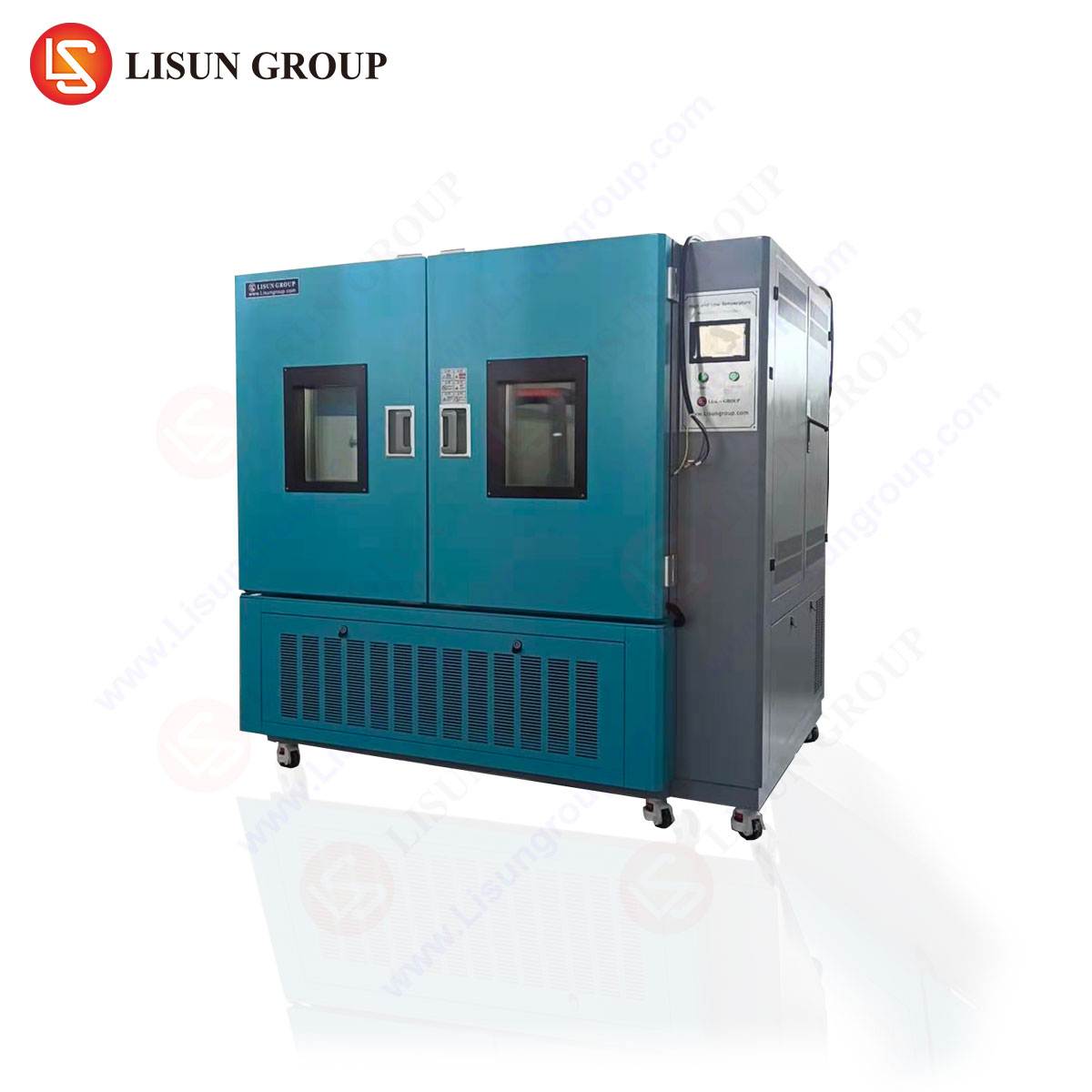
The HLST-500D Thermal Shock Test Chamber: Architecture and Operational Methodology
The LISUN HLST-500D represents a two-basket (also known as a two-zone) thermal shock test chamber, a design optimized for achieving rapid temperature transition rates. Its operational principle is distinct from single-chamber temperature cycling units. The system comprises three key zones: a high temperature chamber, a low temperature chamber, and a transition basket (or carriage) that holds the test specimens.
The testing sequence is mechanically orchestrated. The UUT is initially placed in the transition basket, which resides in a neutral or pre-conditioning zone. Upon test initiation, the basket rapidly transfers the specimens into the high temperature chamber, where they are soaked until thermal equilibrium is achieved throughout the product’s mass. Following this soak period, the basket swiftly moves the specimens to the low temperature chamber for an equivalent soak. This cycle repeats for a pre-programmed number of iterations. The speed of this transfer is critical; the HLST-500D achieves a transition time of less than 10 seconds, ensuring the thermal shock is delivered primarily during the transfer, not during a slow chamber ramp-down.
Key Specifications of the LISUN HLST-500D:
- Test Temperature Range: High Temperature Chamber: +60°C to +200°C; Low Temperature Chamber: -10°C to -65°C (or -80°C depending on configuration).
- Recovery Time: ≤5 minutes (from +150°C to -55°C or vice-versa, under full load).
- Temperature Fluctuation: ±0.5°C.
- Temperature Uniformity: ≤2.0°C.
- Chamber Volume: 500 Liters (effective test space).
- Basket Load Capacity: Typically 30-50 kg, dependent on configuration.
- Control System: Digital programmable controller with data logging and USB interface, compliant with standards requiring precise time-temperature documentation.
This architecture allows for extreme temperature differentials (ΔT) exceeding 200°C to be applied to the specimen in seconds, creating the severe thermo-mechanical stress essential for effective screening.
Industry-Specific Applications and Failure Mode Revelation
The utility of thermal shock testing spans industries where component failure carries significant cost or risk. The HLST-500D’s capacity facilitates testing of larger sub-assemblies, entire products, or batches of components.
-
Automotive Electronics: Modern vehicles contain over a hundred electronic control units (ECUs). A transmission control module may experience under-hood temperatures exceeding 125°C and, in cold climates, ambient startup temperatures below -30°C. Thermal shock testing validates the integrity of ball grid array (BGA) solder joints on these modules, preventing failure due to CTE mismatch between the silicon die, substrate, and PCB. It also tests connectors and wiring harnesses for cracking or contact retraction.
-
Aerospace and Aviation Components: Avionics must function from ground operations in desert heat to high-altitude cruising at -55°C. Thermal shock testing on components like flight data recorders, satellite communication modules, and engine sensors uncovers delamination of multilayer boards, hermetic seal failures in MEMS sensors, and contact fretting in circular connectors.
-
Telecommunications Equipment: 5G base station amplifiers and optical network terminals (ONTs) are deployed in outdoor cabinets subject to wide diurnal temperature swings. Testing with equipment like the HLST-500D accelerates fatigue in coaxial cable connectors, reveals popcorn cracking in overmolded IC packages, and validates the thermal stability of laser diodes used in fiber optics.
-
Medical Devices: Implantable devices like pacemakers and external life-support equipment must have absolute reliability. Thermal shock testing screens for failures in battery seals, biocompatible epoxy encapsulation, and flex circuit interconnects that could be induced by sterilization processes or patient body temperature fluctuations.
-
Lighting Fixtures and Consumer Electronics: LED drivers and high-brightness LED arrays generate significant heat. Rapid thermal cycling tests the integrity of die-attach materials, phosphor layers, and wire bonds within the LED package itself, as well as the power supply’s capacitors and transformers. For consumer electronics like smartphones, it simulates the stress of being left in a car, moving from a hot dashboard to an air-conditioned environment.
-
Electrical Components and Wiring Systems: Circuit breakers, relays, and terminal blocks undergo thermal shock to ensure metal contacts do not warp or lose spring tension, and that insulating housings do not become brittle or crack. Cable assemblies are tested for jacket integrity and the stability of crimped or soldered connections.
Standards Compliance and Testing Regimens
Formal qualification testing is often mandated by international and industry-specific standards, which prescribe precise thermal shock profiles. The HLST-500D is engineered to facilitate compliance with these rigorous protocols.
- MIL-STD-810H, Method 503.6: The U.S. military standard for environmental engineering outlines thermal shock procedures for equipment likely to experience rapid temperature changes during deployment or transport. It defines transfer time requirements and soak criteria.
- IEC 60068-2-14: This International Electrotechnical Commission standard, “Test N: Change of temperature,” provides detailed procedures for both temperature cycling (Test Na) and thermal shock (Test Nb), specifying rates of change, dwell times, and number of cycles.
- JESD22-A104: A JEDEC standard for temperature cycling, widely referenced in the semiconductor industry for component-level testing.
- Automotive Standards: OEMs often have proprietary test specifications derived from standards like ISO 16750 (Road vehicles) or AEC-Q100 (Automotive Electronics Council), which include severe thermal cycling and shock requirements far exceeding commercial-grade specs.
A typical test regimen for an automotive sensor might involve 500 cycles of -40°C to +125°C, with 30-minute dwells at each extreme and a transfer time of <30 seconds. The HLST-500D’s sub-10-second transfer capability and rapid recovery ensure the most severe portion of the profile—the transition—is accurately enforced.
Comparative Advantages in Chamber Design and Data Integrity
The two-basket design of the HLST-500D offers distinct advantages over single-chamber thermal cycling systems. The dedicated high and low temperature chambers are maintained at their target extremes at all times during testing. This eliminates the energy-intensive and time-consuming process of ramping a single chamber between extremes, resulting in significantly faster cycle times, reduced compressor wear, and higher throughput. Furthermore, it provides a truer thermal shock, as the specimen experiences an immediate ambient change rather than a controlled ramp.
Data integrity is paramount. Modern controllers, as featured in this chamber, provide not only precise control but also exhaustive logging of the chamber’s performance and the de facto profile experienced by the test specimen. This audit trail is critical for certification purposes and failure analysis. The ability to program complex profiles with multiple setpoints, dwells, and cycle counts allows engineers to tailor tests to simulate specific real-world scenarios, from the daily cycle of a solar inverter to the intermittent usage profile of industrial control system hardware.
Integration into the Broader Validation Ecosystem
High temperature and thermal shock testing do not exist in isolation. They form a critical link in a chain of environmental tests that may include humidity (often combined as Temperature Humidity Bias, THB), vibration, mechanical shock, and salt spray. The findings from thermal shock testing often inform design for manufacturability (DFM) changes, such as selecting conformal coatings with better elastic properties, specifying underfill materials for BGA components, or redesigning mechanical enclosures to accommodate expansion. For industries like aerospace and medical devices, passing these tests is not just a matter of quality but a regulatory and safety imperative, directly tied to certification and market approval.
FAQ: Thermal Shock Testing and the HLST-500D Chamber
Q1: What is the fundamental difference between thermal shock testing and temperature cycling?
A1: The key distinction lies in the rate of temperature change. Thermal shock testing, as performed by a two-basket chamber like the HLST-500D, subjects the specimen to an extremely rapid transition between two pre-set temperature extremes (e.g., in under 10 seconds). This induces sharp mechanical stress. Temperature cycling typically uses a single chamber that ramps between temperatures at a controlled, slower rate (e.g., 5°C/min), focusing more on gradual thermal fatigue over a higher number of cycles.
Q2: Why is the transfer/recovery time specification so critical for a thermal shock chamber?
A2: The transfer time determines the abruptness of the shock. A longer transfer allows the specimen to partially equilibrate during movement, diluting the test severity. Recovery time—the period for the chamber to return to its target temperature after the specimen basket is inserted—is equally vital. If recovery is slow, the effective “soak” time at the target temperature is compromised, leading to a non-compliant test profile. Fast recovery ensures the specified dwell time is accurately executed.
Q3: Can the HLST-500D be used for testing that requires humidity in conjunction with temperature?
A3: No, the HLST-500D is a dedicated thermal shock chamber designed for dry high and low temperature extremes. Humidity introduces complexity (condensation, ice formation) incompatible with its rapid-transfer, two-basket design. For combined temperature-humidity testing, a separate climatic chamber, such as a model from the GDJS series, is required. These two test types are complementary but executed on specialized equipment.
Q4: What industries most commonly require compliance with MIL-STD-810H thermal shock profiles?
A4: While originating from U.S. defense, MIL-STD-810H is now a widely respected benchmark for ruggedized equipment. Industries with stringent reliability needs frequently reference it, including Aerospace & Defense (avionics, ground support), Telecommunications (outdoor infrastructure), Industrial Control (factory automation in harsh environments), and increasingly, Automotive (for military or heavy-duty vehicles). It represents a high bar for environmental robustness.
Q5: How is test specimen loading determined for a chamber like the HLST-500D?
A5: Loading is constrained by both mass and thermal mass. The basket has a maximum weight capacity (e.g., 50 kg). More critically, the combined thermal mass (heat capacity) of the specimens must not exceed the chamber’s ability to maintain its recovery time specifications. Overloading with dense, metallic products can slow recovery, invalidating the test. Test standards often specify a “loaded” performance requirement, and reputable chamber manufacturers provide guidance on maximum thermal load.