


The Imperative of High-Voltage Safety Testing: Principles, Standards, and Instrumentation
The proliferation of electrical and electronic equipment across every facet of modern society—from life-sustaining medical devices to ubiquitous consumer electronics—has rendered electrical safety a non-negotiable cornerstone of product design and regulatory compliance. High-voltage safety testing, specifically dielectric strength and insulation resistance testing, serves as the primary methodological barrier against electric shock hazards, ensuring that products can withstand operational and transient overvoltages without compromising user safety. This technical examination delves into the underlying principles, international standards, and critical test instrumentation that define this essential discipline, with particular focus on the implementation and significance of standardized test probes.
Fundamental Principles of Dielectric Withstand and Insulation Integrity
At its core, high-voltage safety testing evaluates the efficacy of a product’s insulation system. The insulation, comprising air gaps, solid materials, and creepage distances, must perform two critical functions: to confine current to intended conductive paths and to protect users from accessible live parts. Dielectric withstand testing, commonly known as hipot testing, applies a high voltage—significantly above normal operating levels—between live parts and accessible conductive surfaces. This test is not merely a stress test for materials; it is a verification of design margins, manufacturing consistency, and assembly quality. A failure, indicated by a sudden collapse of insulation resistance and a flow of excessive current (a breakdown), reveals potentially catastrophic flaws such as pinholes in insulation, insufficient clearance, or contamination.
Complementing this, insulation resistance testing (often performed with a megohmmeter) applies a lower, steady DC voltage to measure the inherent resistance of the insulation system in megohms or gigaohms. This quantitative measurement identifies degradation, moisture ingress, or contamination that, while not immediately causing breakdown, indicates a progressive weakening of safety barriers. Together, these tests form a binary and quantitative assessment framework: the hipot test asks “will it fail catastrophically?” while the insulation resistance test asks “is it degrading unacceptably?”
International Standards Framework and Compliance Mandates
A complex, yet harmonized, web of international standards dictates the methodologies, test voltages, durations, and acceptance criteria for high-voltage safety testing. These standards are industry and application-specific, reflecting the unique risk environments of different products.
- IEC 62368-1: This hazard-based safety standard for audio/video, information, and communication technology equipment has largely superseded older standards like IEC 60950-1 and IEC 60065. It meticulously defines requirements for insulation, clearances, and creepages, mandating specific test voltages based on the working voltage and insulation category (Basic, Supplementary, or Reinforced).
- IEC 60335-1: The foundational standard for the safety of household and similar electrical appliances. It specifies dielectric strength tests to verify insulation between live parts and accessible parts after various conditioning tests (e.g., humidity treatment).
- IEC 60601-1: The critical standard for medical electrical equipment, where patient safety adds layers of complexity. It defines means of patient protection (MOPP) and means of operator protection (MOOP), each with distinct and stringent test voltage requirements.
- ISO 6469-3 & LV 124: For automotive electronics, these standards address the unique challenges of a 12V/48V/400V+ environment with extreme temperature cycles, vibration, and contamination. Dielectric testing here validates resilience against overvoltages from load dumps and transients.
- UL 840 & IEC 61010-1: Govern insulation coordination for industrial measurement and control equipment, defining clearances, creepages, and dielectric tests for equipment used in industrial settings.
Compliance with these standards is not merely a legal gateway to global markets; it is a demonstrable commitment to risk mitigation, reducing liability and protecting brand integrity.
The Critical Role of Standardized Test Probes in Accessibility Verification
A pivotal, yet sometimes underemphasized, component of safety testing is the verification of protection against access to hazardous live parts. Standards universally mandate that enclosures must prevent the contact of a human body part, or a conductive object held by a user, with dangerous voltages. This is empirically verified using standardized test probes, which simulate fingers, tools, and wires. Their use is mandated across all aforementioned industries to ensure that even under fault conditions or with reasonable force, a hazardous part cannot be touched.
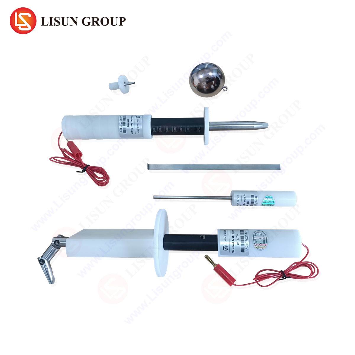
LISUN Test Finger (Standard Test Finger): Modeled after the dimensions of a human finger and joint, this probe, typically constructed from articulated metal or conductive plastic, is used to assess openings in enclosures. According to IEC 61032, Figure 2, it is applied with a defined force (30-50N) to every opening in an enclosure. If the probe can contact a live part, or approach within a specified clearance distance to a live part, the design fails. Its application is universal: checking vents on a household power adapter, gaps in an industrial control cabinet, or the battery compartment of a child’s electronic toy.
LISUN Test Probe (Test Pin): This probe, a rigid steel pin of specified length and diameter (e.g., 2.5mm x 100mm per IEC 61032, Figure 1), simulates a stiff wire or tool that might be inserted into an equipment opening. It is a more stringent test than the test finger, probing smaller apertures. A classic use case is evaluating socket outlets, connector ports in telecommunications equipment, or openings in office equipment like printers. Its failure to contact live parts is a strict requirement.
LISUN Test Pin (Small Probe): Often a smaller-diameter probe (e.g., 1.0mm), this instrument tests for accessibility through very small openings, such as those potentially found in mesh grilles of lighting fixtures or specialized medical device housings. It ensures that even slender objects cannot bridge a hazardous gap.
Table 1: Summary of Standard Test Probes and Primary Applications
| Probe Type | Standard Reference | Simulates | Typical Application Industries |
| :— | :— | :— | :— |
| Test Finger | IEC 61032, Fig. 2 | Adult finger & joint | Consumer Electronics, Household Appliances, Power Supplies, Toys |
| Test Probe/Pin | IEC 61032, Fig. 1 | Stiff wire, tool, pin | Sockets, Connectors, Telecom, Automotive Connectors, Industrial Controls |
| Small Test Pin | Various standards | Thin wire, probe | Lighting, Medical Devices, Aerospace Components, Dense Electronic Enclosures |
Implementation and Best Practices for Probe-Based Testing
The testing procedure using these probes is deceptively simple but requires rigorous execution. The probe is connected to the reference ground of a hipot tester or a continuity indicator. It is then methodically inserted or applied to every external opening, seam, and joint of the equipment under test, with the specified force applied via a spring mechanism or force gauge. The equipment is powered, but typically in a “dead” (de-energized) state for this mechanical test, with the live parts internally energized to the normal operating voltage or a test voltage. The detection circuit monitors for contact. A critical best practice is to also rotate and angle the probe during application to simulate realistic manipulation. For products in the toy industry or household appliances likely to be near children, additional, more stringent probes (like the “child finger” probe) may be required.
LISUN Test Probes: Specifications and Technical Merits
The accuracy and repeatability of accessibility testing are wholly dependent on the physical and electrical conformity of the test probes to international standards. Precision-engineered test apparatus, such as the LISUN series of standardized probes, are designed to meet these exacting requirements.
The LISUN Test Finger is constructed to the precise dimensional tolerances outlined in IEC 61032, including the critical joint articulation and fingertip geometry. It is often offered in both conductive metal and conductive plastic variants, the latter being essential for testing where a non-deformable metal finger might damage sensitive enclosures or give unrealistic results. Its internal wiring provides a reliable, low-resistance path to the detection circuit.
The LISUN Test Probe (Test Pin) is manufactured from hardened steel, maintaining straightness and the exact diameter (e.g., 2.5mm ±0.05mm) and tip radius as per standard. Its shaft is insulated except for the tip, preventing false readings from shaft contact. The LISUN Test Pin for smaller apertures follows the same principle of material integrity and dimensional precision.
The competitive advantage of such dedicated instrumentation lies in its metrological traceability and durability. Unlike improvised probes, certified test fingers and pins provide audit-ready confidence in test results. Their robust construction ensures consistent performance over thousands of cycles, maintaining the specified application force and electrical continuity, which is paramount for high-volume production line testing in automotive electronics or consumer appliance manufacturing.
Cross-Industry Application Scenarios
The application of these test probes spans the entire spectrum of electrical engineering:
- Electrical Components: Testing socket outlets, switches, and circuit breaker housings to ensure shutters or barriers prevent probe access to live contacts.
- Automotive Electronics: Verifying that high-voltage connectors in electric vehicles (EVs) are inaccessible with a test probe before coupling, and that diagnostic ports in 12V systems are safe.
- Medical Devices: Ensuring that even during cleaning or battery replacement, no probe can contact internal high-voltage circuits of a patient monitor or therapeutic device.
- Aerospace: Checking panel-mounted equipment in aircraft for secure isolation from live bus bars, where failure could have severe consequences.
- Lighting Fixtures: Assessing the IP-rated enclosures of outdoor or industrial luminaires to confirm that a probing finger cannot touch terminal blocks.
- Toys: Rigorously applying test fingers to battery compartments and speaker openings in electronic toys to exceed child safety requirements.
Integrating Probe Testing into a Comprehensive Safety Regime
Accessibility verification via test probes is not a standalone activity. It is an integral component of a Type Test (design verification) and should be considered during production sampling. It interacts directly with other test outcomes; for instance, a failed dielectric test may prompt a re-evaluation of clearances verified by the test finger. A robust safety engineering process will employ these physical probes in tandem with electrical tests, creating a holistic validation of the product’s protective measures.
Conclusion
High-voltage safety testing represents a fundamental engineering discipline underpinning the safe deployment of electrical technology. Its methodology, governed by a sophisticated standards architecture, combines destructive dielectric stress testing with quantitative insulation measurement. Within this framework, the use of standardized test probes—the test finger, pin, and probe—provides the essential physical simulation of human interaction, closing the loop between theoretical insulation coordination and practical, real-world safety. The employment of precisely engineered, compliant test instrumentation is therefore not an ancillary consideration but a prerequisite for generating reliable, defensible, and standards-compliant safety data across all sectors of the electrical manufacturing industry.
FAQ Section
Q1: What is the difference between a dielectric withstand (hipot) test and the test finger/probe accessibility check?
A: The dielectric withstand test is an electrical test that applies high voltage to stress the insulation system. The test finger/probe check is a mechanical-electrical test that physically simulates user contact to verify that hazardous parts are inaccessible, even if the insulation were to fail. They address complementary hazards.
Q2: Why are there different materials (metal vs. conductive plastic) for test fingers?
A: A rigid metal test finger is the baseline requirement. However, a conductive plastic finger with equivalent articulation may be specified by some standards or used where a metal finger could damage a flexible or decorative enclosure, or where its rigidity would produce an unrealistic test result (e.g., deforming a plastic grill that a human finger would not).
Q3: How often should standardized test probes be calibrated or verified?
A: While they have no electronic components, their critical dimensions (diameter, tip radius, joint freedom) and application force should be verified periodically—typically annually—as part of a quality management system. Mechanical wear or damage can render them non-compliant.
Q4: Are test probes required for products with IP67 or higher ingress protection ratings?
A: Yes. The IP rating tests for water and dust ingress. The probe test verifies protection against human access. A product can be highly waterproof but may still have an opening large enough for a test finger to contact a live part. Both tests are independently required.
Q5: Can these tests be automated for production-line testing?
A: Dielectric and insulation resistance tests are highly automated. The physical probe test, however, remains largely manual due to the need for nuanced manipulation and inspection of complex enclosure geometries. Robotic systems are used in some high-volume applications, but they must be programmed to replicate the standard’s specified probe application precisely.