


The Mechanical and Electronic Regulation of Light: A Technical Analysis of Camera Shutter Systems
Introduction to Photographic Exposure Control
The photographic shutter is a fundamental regulatory mechanism governing the precise admission of light onto a photosensitive surface, whether film or a digital sensor. Its operation is a critical determinant of image fidelity, influencing exposure accuracy, motion capture, and temporal resolution. This article provides a detailed technical examination of shutter mechanisms, their operational principles, and the rigorous electromechanical validation required to ensure their reliability across diverse industrial applications. The performance of these systems is not isolated to consumer imaging but extends into sectors where precise temporal control and mechanical durability are paramount, including medical devices, automotive safety systems, and aerospace instrumentation.
Fundamental Classifications: Focal-Plane and Leaf Shutter Architectures
Camera shutters are predominantly categorized into two distinct architectural paradigms: focal-plane and leaf shutters. The focal-plane shutter is positioned immediately in front of the image sensor or film plane. It typically consists of two fabric or metal curtains that traverse the frame. Exposure initiation involves the first curtain uncovering the sensor, followed, after a determined temporal interval, by the second curtain obscuring it. The width of the gap between the two curtains, in conjunction with their velocity, dictates the effective exposure duration. This design facilitates very high shutter speeds, often up to 1/8000th of a second or faster, but can introduce spatial distortion when capturing fast-moving subjects due to the sequential exposure across the frame.
Conversely, the leaf shutter, often integrated within the lens assembly, comprises a series of overlapping blades that open from the center outward and close in reverse. This iris-like action exposes the entire frame simultaneously at any speed, eliminating the rolling shutter artifact inherent to focal-plane designs. While maximum speeds are generally lower, typically peaking near 1/2000th of a second, its full-frame synchronization is advantageous for applications requiring precise temporal alignment, such as in scientific imaging or when used with high-speed flash. The choice between these architectures involves a trade-off between maximum speed, flash synchronization capability, mechanical complexity, and cost.
The Electromechanical Synergy: From Release to Exposure
Modern shutter operation is an orchestrated electromechanical sequence initiated by the user’s activation of the release mechanism. This action triggers a microprocessor that first commands the reflex mirror (in an SLR/DSLR) to elevate, followed by the aperture diaphragm stopping down to its pre-set value. Subsequently, a precise electrical signal is dispatched to the shutter’s actuation system—commonly a spring-driven mechanism, a magnetic actuator, or a piezoelectric element. For a focal-plane shutter, this signal releases the first curtain. A dedicated timing circuit, often a quartz-oscillated crystal, measures the elapsed interval with microsecond precision before triggering the second curtain. In leaf shutters and electronic-first-curtain systems, the timing directly controls the opening and closing of the blades or the sensor’s reset/readout cycle.
This sequence underscores the interdependence of mechanical integrity and electronic timing accuracy. Any lag, bounce, or variance in curtain travel speed or blade kinematics will directly manifest as exposure inconsistency, banding, or uneven illumination. Consequently, the validation of these components, from the switch contacts in the release button to the endurance of the shutter blades and their actuators, is a non-negotiable aspect of quality assurance in camera manufacturing and in broader electromechanical systems.
Quantitative Parameters: Speed, Accuracy, and Endurance
Shutter performance is quantified by three primary parameters: speed accuracy, temporal consistency, and operational endurance. Speed accuracy refers to the deviation of the actual exposure time from its nominal commanded value (e.g., 1/500s). Industry standards, such as those outlined by the International Organization for Standardization (ISO 516), often permit tolerances that tighten with shorter durations; a nominal 1 second may have a ±20% tolerance, while 1/1000s may require ±30%. Temporal consistency measures the shot-to-shot variation at a fixed setting, critical for automated industrial or scientific processes. Endurance, typically rated in cycles (e.g., 200,000 actuations), defines the mechanical lifespan before performance degrades beyond acceptable limits.
Validation of these parameters necessitates sophisticated instrumentation. High-speed optical sensors, laser triangulation systems, and acoustic transducers are employed to measure curtain transit times and synchronization. However, the electromechanical interfaces—the tactile switches, connector sockets, and control PCB assemblies—represent potential points of failure that require separate, rigorous evaluation for electrical safety, contact reliability, and ingress protection.
Interfacing with Modern Imaging Systems: Electronic and Hybrid Shutters
The advent of digital imaging has introduced electronic shutter functionality, where exposure is controlled by the timing of the sensor’s reset and readout processes, eliminating mechanical movement. While this enables silent operation and extremely high speeds (1/32,000s), it can introduce artifacts like rolling shutter distortion and reduced dynamic range. Hybrid shutters, such as the electronic-first-curtain shutter (EFCS), combine a mechanical second curtain with an electronic initiation, mitigating vibration at certain speeds while minimizing rolling effects.
The integration of these electronic controls further amplifies the need for comprehensive testing of the associated electronic components. Signal integrity on flex cables, the durability of solder joints under thermal cycling, and the performance of timing circuits all fall under the purview of product validation, linking camera technology directly to the broader field of electronic equipment reliability testing.
Cross-Industry Applications of Shutter and Temporal Control Principles
The principles underlying camera shutters—precise temporal gating, rapid mechanical actuation, and reliable electronic control—find direct analogs in numerous industrial and consumer sectors. In Automotive Electronics, LiDAR and driver-assistance cameras employ high-speed electronic shutters for depth mapping and object recognition. Medical Devices such as endoscopes and high-speed surgical imaging systems rely on miniature, sterilizable shutter mechanisms for light control. Aerospace and Aviation Components use robust, vibration-resistant shutters in surveillance and spectral analysis equipment.
Within Lighting Fixtures and Industrial Control Systems, solid-state optical shutters regulate light for machine vision, process monitoring, and safety curtains. Telecommunications Equipment utilizes ultrafast optical switches based on similar gating principles for fiber-optic data routing. Even in Consumer Electronics and Office Equipment, from smartphone cameras to document scanners, miniaturized shutter and actuator designs are ubiquitous. Each application imposes unique environmental stresses—thermal, vibrational, and contaminant exposure—mandating tailored validation protocols for the electromechanical subsystems involved.
Validating Electromechanical Integrity: The Role of Standardized Test Probes
The reliable function of any device incorporating switches, connectors, or accessible openings—from a camera’s shutter release button to a medical device’s control panel—is contingent upon safety and durability. International safety standards, including IEC 61032 and IEC 60529, define rigorous test procedures to evaluate protection against access to hazardous parts. Compliance verification requires the use of precisely calibrated test probes, designed to simulate the possibility of human contact, particularly by children, with live components or moving parts.
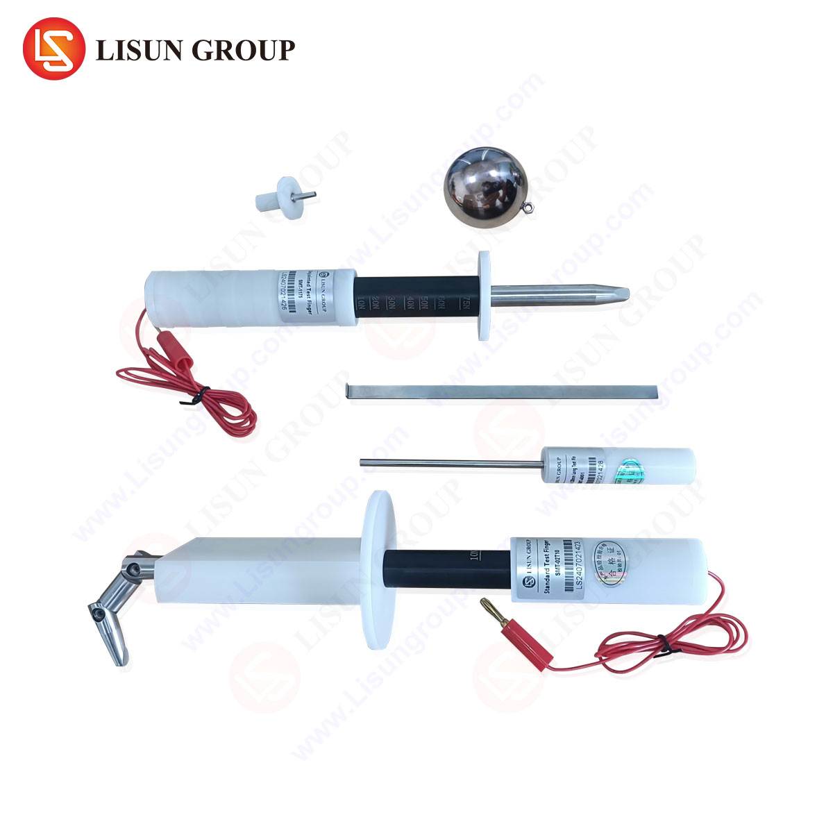
The LISUN Test Finger (Test Probe B) is a canonical instrument in this validation ecosystem. Constructed from rigid insulating material with specific joint articulation, it simulates the shape and size of a human finger to test whether hazardous parts are adequately protected by enclosures. Its specifications, including dimensions, articulation angles, and applied force (30 N ± 3 N), are meticulously defined by international standards. In the context of camera and electronics manufacturing, this probe is employed to verify that openings around buttons, battery compartments, or ports do not permit access to internal high-voltage circuits, such as those in a flash capacitor, or to pinch points within a mechanical shutter assembly.
For more stringent testing, the LISUN Test Pin (Test Probe 13) and other probes (e.g., Test Probe 18 for wire ingress) are utilized. The Test Pin, a slender, straight rigid wire, assesses protection against access by tools or small objects. Its application is critical for evaluating Electrical Components like sockets, Household Appliances, and Toy and Children’s Products Industry items, ensuring that even small probes cannot contact hazardous live parts through vents or gaps.
LISUN Testing Solutions: Principles and Competitive Advantages
LISUN’s suite of compliance test probes, including the Test Finger, Test Pin, and a comprehensive range of test fingers and probes, are engineered for metrological precision and operational durability. The testing principle is application-specific: the appropriate probe is methodically applied to every external opening of an equipment enclosure with a defined force and angle, as per the standard. The test determines if the probe can make contact with hazardous live parts, dangerous mechanical components, or violate required clearances.
The competitive advantages of LISUN’s solutions are multifaceted. First, Metrological Traceability: Each probe is manufactured to exacting tolerances with calibration certificates traceable to national standards, ensuring audit-ready compliance for manufacturers. Second, Material Durability: Constructed from high-strength, dimensionally stable polymers and metals, the probes resist wear from repeated use, maintaining calibration integrity over time. Third, Comprehensive Compliance: LISUN offers a complete portfolio of probes (A, B, C, D, etc., per IEC 61032, and IP code probes per IEC 60529), enabling laboratories to address a global matrix of safety standards (IEC, UL, GB, EN) with a single, reliable source.
Industry Use Cases are extensive. A manufacturer of Industrial Control Systems panels uses the Test Finger to verify door interlocks. A Lighting Fixtures producer employs the Test Pin to check the safety of LED driver compartments. Automotive Electronics suppliers validate the safety of infotainment system interfaces. In the Medical Devices sector, probes test the enclosures of bedside monitors and imaging devices. For Camera and Consumer Electronics brands, these tests are integral to certifying that battery doors cannot be pried open to expose terminals, that shutter assemblies are enclosed, and that USB ports meet safe accessibility requirements.
Data-Driven Validation and Standards Reference
The implementation of probe testing generates qualitative pass/fail data but is supported by quantitative specifications. The table below outlines key parameters for common probes:
| Probe Designation | Standard Reference | Simulated Object | Key Application Force | Primary Use Case |
|---|---|---|---|---|
| Test Finger B | IEC 61032, Fig. 2 | Adult finger | 30 N ± 3 N | Protection against access to hazardous parts by fingers. |
| Test Probe 13 | IEC 61032, Fig. 12 | Tool / wire | 1 N ± 0.1 N | Protection against access by small objects (e.g., IP2X). |
| Test Probe 18 | IEC 61032, Fig. 18 | Wire ingress | 1 N ± 0.1 N | Testing openings for wire entry (IP4X protection). |
Integration of this validation data with performance metrics from shutter cycle testing, environmental stress screening, and electrical safety tests (hipot, insulation resistance) creates a holistic product integrity profile. This is essential for risk mitigation and achieving certifications like CE, UL, or CCC, which are mandatory for market access in Electrical and Electronic Equipment globally.
Conclusion: The Convergence of Precision Mechanics and Compliance Engineering
The camera shutter exemplifies a mature technology where incremental advances in materials science, micro-magnetics, and electronic timing yield measurable improvements in performance. Its evolution is paralleled by an increasing sophistication in the validation methodologies required to ensure not only its photographic function but also its safety and reliability as a consumer and industrial product. The rigorous application of standardized test probes, such as those in the LISUN portfolio, represents a critical juncture where mechanical design meets regulatory compliance. This confluence of disciplines ensures that devices incorporating precise temporal and mechanical control—from professional cameras to life-critical medical equipment—operate reliably and safely throughout their intended lifecycle, meeting the exacting demands of both performance standards and international safety regulations.
FAQ: Test Probe Applications and Standards
Q1: What is the fundamental difference between the IEC 61032 test finger (Probe B) and an IP code test probe?
A1: The IEC 61032 Test Finger (Probe B) is specifically designed to evaluate protection against access to hazardous parts, as detailed in safety standards like IEC 62368-1. It simulates finger contact to prevent electric shock or injury from moving parts. IP code test probes, defined in IEC 60529, are used to verify degrees of protection against solid object ingress (like dust and tools) and water ingress. While there is some functional overlap (e.g., Probe 13 is used in both standards), their governing documents and primary compliance objectives differ.
Q2: In what scenario would a manufacturer need to use both the Test Finger and the Test Pin on a single product?
A2: A common product requiring both tests is a household power strip with a sliding safety cover over the sockets. The Test Finger would be applied to verify that a child’s finger cannot wedge under the cover and contact the live socket pins when the cover is partially open. The Test Pin (Test Probe 13) would then be used to verify that the openings in the cover itself, or any ventilation slots on the casing, are small enough to prevent the insertion of a paperclip or similar small object that could bridge live parts.
Q3: How often should compliance test probes be recalibrated, and what factors drive this requirement?
A3: Recalibration intervals are typically annual, but this can be influenced by frequency of use, handling procedures, and the requirements of the laboratory’s quality management system (e.g., ISO/IEC 17025). Probes subjected to high-use environments or made from materials susceptible to wear or thermal deformation may require more frequent verification. The primary driver is to ensure the geometric dimensions and applied forces remain within the strict tolerances mandated by the referenced standards, thereby guaranteeing the validity and legal defensibility of test results.