


A Methodological Framework for the Verification of Bipolar Plug Insertion Integrity
Introduction: The Criticality of Insertion Force Verification in Electrical Safety
Within the domain of electrical connectors, the seemingly simple act of inserting a plug into a socket constitutes a critical interface where performance, safety, and longevity converge. For bipolar plugs and sockets, ubiquitous in residential, commercial, and industrial applications, the mechanical characteristics of this insertion—specifically the required force—are not arbitrary. They are precisely defined by international standards such as IEC 60884-1, BS 1363, and UL 498. These specifications exist to ensure a secure electrical connection that minimizes contact resistance, prevents overheating, and withstands the mechanical stresses of normal use and occasional misuse. Verification of plug insertion force is therefore a non-negotiable component of quality assurance, product certification, and ongoing manufacturing control. This article delineates a formalized methodology for this verification process, emphasizing the role of specialized instrumentation in achieving reliable, repeatable, and standards-compliant results.
Defining the Parameters: Insertion and Withdrawal Force Specifications
The verification process begins with a clear understanding of the parameters under test. Insertion force is the maximum axial force required to fully engage a plug into a compliant socket-outlet. Conversely, withdrawal force is the force needed to disengage the plug. Standards prescribe allowable ranges for both. For instance, a common specification for a standard 10A/250V bipolar plug may dictate a maximum insertion force of 40N and a minimum withdrawal force of 2.5N. Exceeding the maximum insertion force can indicate design flaws, poor tolerance stacking, or manufacturing defects in the plug’s pins or the socket’s contacts, leading to user difficulty and potential damage. A withdrawal force below the minimum threshold signals insufficient contact pressure, risking a high-resistance connection that can overheat under load, posing a fire hazard. The precise values are contingent upon the plug’s rating, pin geometry, and the applicable national or international standard.
The Instrumentation Imperative: Introduction to LISUN Gauges for Plugs and Sockets
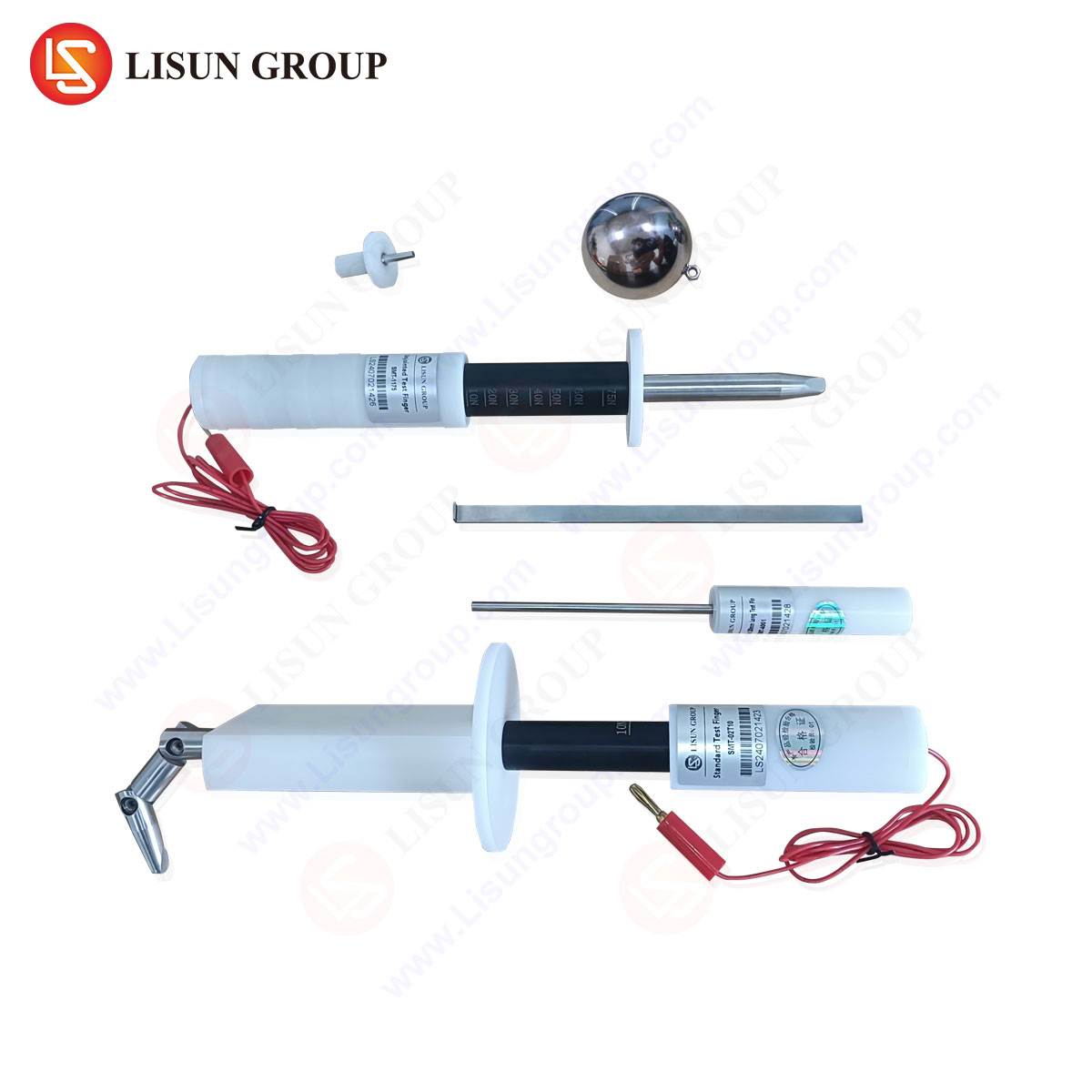
Accurate measurement of these forces necessitates instrumentation designed for the purpose. General-purpose force gauges lack the specialized fixtures and standardized test protocols required for consistent results. This is where dedicated plug and socket gauges, such as the LISUN series, become indispensable. These devices are engineered specifically to verify the mechanical safety of plugs, socket-outlets, and switches in accordance with the major global standards. A typical LISUN gauge system comprises a precision electromechanical or motorized test stand, a high-accuracy force sensor, and interchangeable, standards-compliant test fixtures that simulate the geometry and spring characteristics of a reference socket.
Specifications and Testing Principles:
The core of the LISUN gauge is its force measurement system, often featuring a resolution of 0.1N and an accuracy within ±0.5% of full scale. The test stand provides controlled, linear movement at a specified speed, typically 30 mm/min, as mandated by standards to ensure kinetic conditions do not influence the static force reading. The critical component is the test finger or adapter. For bipolar plug testing, this is a simulated socket outlet with contact tubes that meet the exact dimensional and material specifications (e.g., phosphor bronze) of the standard. The plug under test is mounted in a fixture on the moving crosshead, which then drives the plug pins into the static test socket. The system’s software records the entire force-distance curve, identifying the peak force as the insertion force. For withdrawal, the process is reversed.
Executing the Verification Protocol: A Stepwise Procedure
A rigorous verification protocol eliminates operator variance and ensures data integrity.
- Apparatus Calibration and Setup: Prior to testing, the force gauge and displacement system must be calibrated traceably to national standards. The appropriate test socket fixture for the standard being assessed (e.g., BS 1363, AS/NZS 3112, CEE 7) is installed.
- Plug Preparation and Mounting: The plug sample, conditioned to room temperature as per standard requirements, is securely fastened into the plug holder. The alignment is crucial; the plug’s pins must be parallel to the direction of travel and centered on the entry of the test socket tubes.
- Test Initiation and Data Acquisition: The test cycle is initiated. The crosshead advances, and the plug pins enter the contact tubes. The software records the rising force profile. Friction and the deformation of the socket contacts contribute to the curve. The peak value observed just before full insertion is the recorded insertion force.
- Withdrawal Force Measurement: After a brief dwell at the fully inserted position, the crosshead retracts. The force profile during retraction is recorded, with the peak withdrawal force (often occurring at the point of initial pin disengagement from the contact grip) being identified.
- Analysis and Conformance Checking: The measured peak insertion and withdrawal forces are compared against the limits prescribed in the relevant standard. A single sample is insufficient; statistical process control typically requires a sample lot (e.g., 10-20 units) to verify process capability (Cp/Cpk).
Industry Applications and Use Cases for Systematic Verification
The application of plug insertion force verification spans the entire product lifecycle.
- Research & Development and Design Validation: Engineers use this data to optimize pin taper, contact spring design, and housing geometry. Iterative testing during prototyping ensures the design will meet standards before tooling is committed.
- Production Line Quality Control: In manufacturing, periodic sampling and testing using systems like the LISUN gauge provide statistical process control (SPC) data. Trends in increasing insertion force can signal tooling wear in pin stamping or molding, allowing for preventative maintenance before non-conforming products are produced.
- Third-Party Certification and Safety Agency Testing: Nationally Recognized Testing Laboratories (NRTLs) and certification bodies (e.g., UL, Intertek, TÜV) rely on this precise measurement as a pass/fail criterion for granting safety marks.
- Incoming Quality Inspection (IQC) for Component Procurement: Manufacturers of socket-outlets or complete assemblies will verify that purchased plugs from subcontractors meet mechanical specifications, ensuring the quality of their final product.
Comparative Advantages of Dedicated Verification Systems
While alternative methods exist, such as simple spring scales or un-fixtured push-pull gauges, they introduce significant error. Hand-held methods suffer from operator-induced angular forces and inconsistent speed. The competitive advantage of a dedicated system like the LISUN gauge lies in its standardization and repeatability.
- Standardized Fixturing: The use of certified, dimensionally perfect test sockets ensures every test replicates the conditions defined by the standard, which is impossible with a real socket that itself has tolerances.
- Automated Control and Data Logging: Automated travel and speed control remove operator influence. Integrated software provides objective data capture, curve analysis, and report generation, creating an auditable trail for quality systems like ISO 9001.
- Enhanced Repeatability and Reproducibility (R&R): The system’s design minimizes measurement variation, leading to superior Gage R&R studies, which is a cornerstone of reliable quality control data.
Interpreting Force-Distance Curves for Diagnostic Insights
The force-distance curve is a rich source of diagnostic information beyond the simple peak values. A well-designed plug will show a smooth, progressively increasing curve. Anomalies provide direct insight into problems:
- A Sharp Force Spike Early in Insertion: This may indicate misalignment, burrs on the plug pins, or an undersized entry chamfer on the plug housing.
- Excessive Force Followed by a Drop (Hysteresis): Can suggest plastic deformation or damage occurring to the socket contacts during the test, indicating poor pin or contact material ductility.
- An Irregular or Noisy Curve: Often points to surface contamination, poor plating, or roughness on the pin surfaces.
Integration with Broader Compliance Testing Regimes
Insertion force verification is rarely an isolated test. It is part of a comprehensive suite of mechanical, electrical, and thermal tests. The data from a LISUN gauge often correlates with results from other tests. For example, a plug with a low withdrawal force may subsequently fail the temperature rise test under load due to high contact resistance. Similarly, plugs subjected to durability testing (insertion/withdrawal cycles) can be periodically checked with the gauge to monitor contact wear and predict end-of-life performance.
Conclusion
The verification of bipolar plug insertion integrity is a fundamental engineering assessment with direct implications for safety and performance. Moving beyond subjective assessment to a quantifiable, standards-based methodology is essential. Employing dedicated, precision instrumentation such as LISUN Gauges for Plugs and Sockets transforms this verification from a qualitative check into a controlled, data-driven process. This approach provides manufacturers, test labs, and certification bodies with the objective evidence required to ensure products are safe, reliable, and fully compliant with international safety standards, ultimately contributing to the prevention of electrical failures and the protection of end-users.
FAQ Section
Q1: Can a single LISUN gauge system test plugs conforming to different international standards?
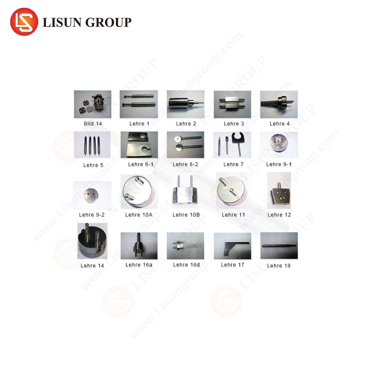
A1: Yes, provided the system is equipped with the corresponding suite of interchangeable test fixtures. Each standard (e.g., BS 1363, IEC Type C, AS/NZS 3112) defines unique pin dimensions and socket contact specifications. The core force measurement unit is universal, but the test fingers/socket adapters are specific to each plug type. A comprehensive system allows for quick fixture changes to accommodate a global product portfolio.
Q2: How frequently should the test socket fixtures (test fingers) be calibrated or replaced?
A2: The test fixtures are precision components subject to wear. Calibration intervals should be established based on usage frequency, typically every 6 to 12 months for active labs. The fixtures should also be inspected regularly for visible wear or damage. Excessive wear will artificially increase insertion force readings and must be corrected to maintain measurement integrity.
Q3: What sample size is statistically valid for production batch acceptance testing?
A3: There is no universal number; it depends on the production volume, historical process capability, and the acceptable quality level (AQL). Common practice in quality control involves using ANSI/ASQ Z1.4 or similar sampling plans. For process validation or capability studies, sample sizes of 30-50 units are often recommended to achieve meaningful statistical power.
Q4: Beyond insertion/withdrawal force, what other mechanical tests can this equipment perform?
A4: With appropriate fixtures, the same force measurement platform can be used for a variety of related tests: cable pull tests (strain relief effectiveness), impact tests on plugs and sockets, operating force for switches, and even compression tests on protective shutters in socket-outlets. The system’s versatility makes it a core tool for mechanical safety testing.
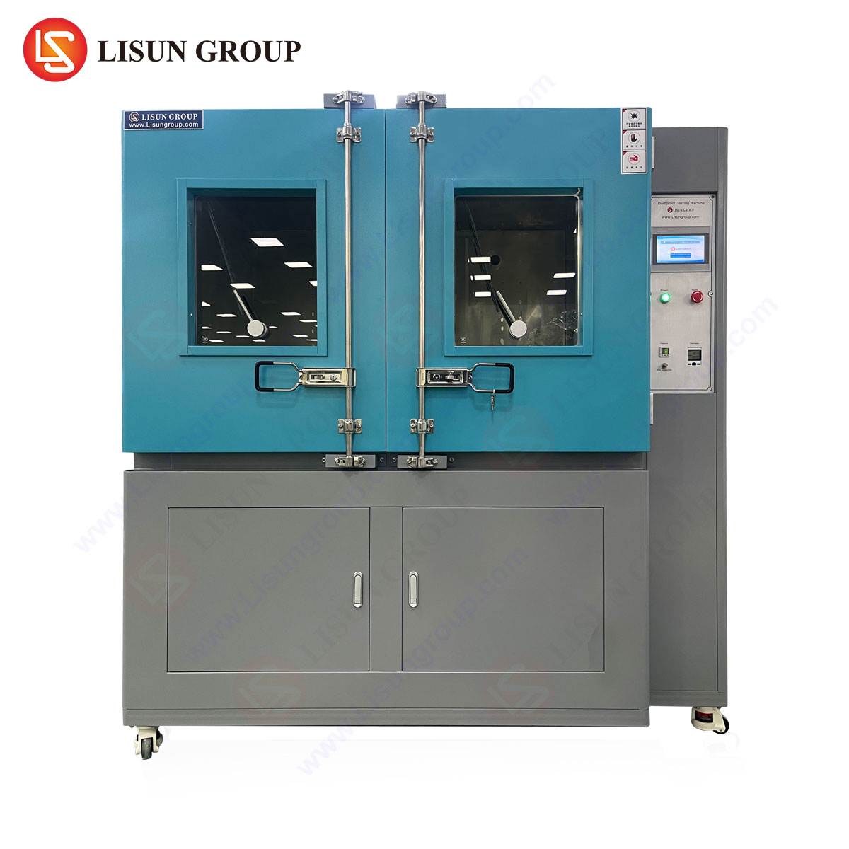
Q5: How does environmental conditioning, as required by some standards, affect insertion force measurements?
A5: Significantly. Standards often mandate testing samples after conditioning in high temperature (e.g., 70°C) and low temperature (e.g., -15°C) chambers. Plastic components expand or contract, and metal spring properties change. A plug may pass insertion force at room temperature but fail at low temperatures due to housing shrinkage or lubricant stiffening. Comprehensive verification must include testing under these conditioned states.