


The Role of Standardized Mechanical Probes in Hazard-Based Safety Engineering
The paradigm of product safety evaluation has progressively shifted from a prescriptive, hazard-based approach to a more holistic, performance-oriented methodology. This evolution is codified within the IEC 62368-1 standard, an overarching framework for the safety of audio/video, information, and communication technology equipment. Central to the application of this standard is the concept of Hazard-Based Safety Engineering (HBSE), which necessitates the identification of energy sources and the provision of safeguards against potential bodily injury. The practical verification of these safeguards against accessible hazardous parts is conducted using a suite of standardized test probes. These instruments, while mechanically simple, are critical for ensuring compliance and mitigating risks across a vast spectrum of industries.
Fundamental Principles of Accessibility Testing Under IEC 62368-1
IEC 62368-1 fundamentally reclassifies energy sources into three primary classes: Class 1 (non-hazardous), Class 2 (hazardous, but not causing pain or injury under normal conditions), and Class 3 (hazardous, capable of causing pain or injury). A core tenet of the standard is that safeguards must be provided to protect persons from accessing these energy sources. “Accessibility” is not a subjective term; it is quantitatively defined by the ability of a specified test probe to contact a hazardous live part or a moving component.
The standard delineates several types of probes, each designed to simulate a specific part of the human body or a common object that could be inserted into equipment. The Jointed Test Finger (Test Probe B) simulates a user’s finger, the Test Pin (Test Probe 13) simulates a slender object like a wire or jewelry, and the Object Probe (Test Probe 18) simulates a small, rigid sphere. The application of these probes is not arbitrary; it is dictated by the equipment’s enclosure openings, the nature of the potential hazard, and the intended or foreseeable use of the product. The failure criterion is unequivocal: if a hazardous part is contacted by the specified probe, the design is deemed non-compliant, necessitating a redesign of the enclosure, the addition of barriers, or the implementation of other protective measures.
Anatomizing the IEC 62368 Test Probe Kit: Specifications and Applications
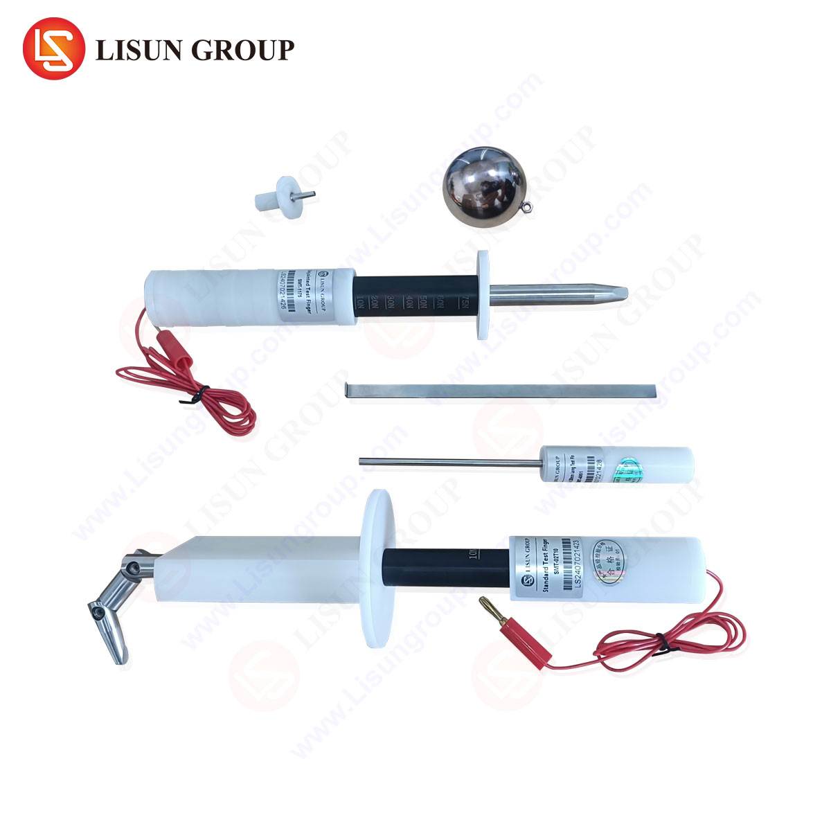
A comprehensive IEC 62368 test probe kit is an assemblage of precision tools, each machined to exacting dimensional tolerances as stipulated by the standard. The kit typically includes the Jointed Test Finger (Probe B), the Test Pin (Probe 13), and the Object Probe (Probe 18), among others relevant to specific clauses.
The Jointed Test Finger is engineered to replicate the size and articulation of an adult human finger. Its design incorporates two joints, allowing it to mimic the natural bending motion, and is constructed from materials such as aluminum or stainless steel with an insulating link. It is applied with a force of 30 N ± 3 N to any opening in an enclosure. Its primary function is to verify that live parts at hazardous voltage levels (e.g., above 60 V DC or 42.4 V peak AC) or dangerous moving parts (like fans) cannot be touched.
The Test Pin, a rigid, straight pin, represents a more severe test of accessibility. It is designed to probe small openings, slots, and gaps that a finger might not enter but a piece of wire, a paperclip, or a child’s probing object could. With a diameter of 2.5 mm and a rounded tip, it is applied with a force of 1 N ± 0.1 N. Its ability to contact a hazardous part through a vent or a poorly designed connector opening is a common cause of compliance failure.
The Object Probe, a 12 mm diameter sphere, simulates small, rigid objects that might be dropped or poked into equipment. It is particularly relevant for testing the safety of openings where a small sphere could bypass a protective barrier and contact a hazardous part.
LISUN‘s Implementation of Standardized Test Probes: A Case Study in Precision
LISUN’s range of IEC 62368 Test Probe Kits exemplifies the rigorous application of these principles. Their product line, including the LISUN Test Finger, Test Probe, and Test Pin, is manufactured with a focus on metrological accuracy and durability, which are non-negotiable for repeatable and reliable safety testing.
LISUN Test Finger (Jointed Test Finger):
Constructed from high-strength, anodized aluminum or stainless steel, the LISUN Test Finger features precisely machined joints that provide realistic articulation without excessive play. The insulating handle ensures the operator’s safety during testing. Its dimensions are strictly controlled to conform to the standard’s requirement of a 12 mm diameter, 80 mm length, and a 90° articulation range. This probe is indispensable for testing household appliances, power strips, industrial control cabinets, and automotive electronic control units (ECUs) to ensure that service panels and ventilation grilles do not permit finger access to internal wiring or busbars.
LISUN Test Pin:
The LISUN Test Pin is a hardened steel pin, ground to a perfect 2.5 mm diameter with a hemispherical tip of radius 1.25 mm. The application force is calibrated using a precision spring mechanism to ensure the 1 N force is consistently applied. This probe is critical for evaluating the safety of USB ports, communication jacks on telecommunications equipment, and the gaps in toy enclosures, where a child might insert a metallic object.
LISUN Test Probe Kits:
LISUN provides these probes as part of a consolidated kit, which often includes application accessories like force gauges and mounting fixtures. The kits are supplied with a calibration certificate traceable to national standards, a necessity for accredited testing laboratories. The competitive advantage of the LISUN kit lies in its comprehensive documentation, material quality that resists wear over thousands of cycles, and its adherence to the geometric tolerances that are often the source of variance between different manufacturers’ probes.
Cross-Industry Application Scenarios for Mechanical Probe Testing
The application of these test probes transcends the traditional IT and AV equipment, permeating nearly every sector involving electrified or mechanical products.
- Electrical and Electronic Equipment & Household Appliances: For a washing machine’s control panel or a dishwasher’s door switch, the jointed test finger ensures that live terminals are inaccessible after the outer casing is removed for service. The test pin verifies that small openings around button shafts are safe.
- Automotive Electronics: In the design of an electric vehicle’s charging port or an infotainment system, probes are used to ensure that high-voltage DC terminals (Class 3 energy source) are inaccessible without a tool, and that low-voltage connectors cannot be probed by a user with a metallic object.
- Lighting Fixtures: LED drivers and ballasts housed within luminaires are tested to ensure that their enclosures prevent access to capacitors and primary-side circuits, even when the diffuser is removed for maintenance.
- Medical Devices: Patient-connected medical devices, such as dialysis machines or patient monitors, undergo rigorous probe testing to prevent any chance of electrical shock, ensuring that even during a fault condition, the enclosure provides robust protection.
- Aerospace and Aviation Components: In-flight entertainment systems and cockpit control modules are tested to withstand probing, ensuring operational integrity and safety in environments where vibration and user interaction are constant factors.
- Toy and Children’s Products Industry: This sector demands the most stringent application of the test pin and object probe. Battery compartments must be designed to be tamper-resistant, preventing a child from inserting a pin and contacting the battery terminals or internal circuitry.
Quantifying Safety: Test Procedures and Pass/Fail Criteria
The testing procedure is a systematic process. The equipment under test (EUT) is placed in its most unfavorable configuration—with doors open, covers removed as per instructions, and adjustable parts positioned to create the largest possible openings. The appropriate probe is selected based on the size and nature of the opening.
The probe is then applied with the specified force, attempting to contact any hazardous part. The test is conducted from every possible angle and direction. To objectively determine contact, a “contact indicator” circuit is often used. This typically consists of a low-voltage (e.g., 40V to 50V) source in series with a visual or audible indicator lamp. The probe itself is connected to one side of this circuit, while the hazardous part is connected to the other. If the probe makes electrical contact with the part, the circuit is completed, and the indicator activates, signaling a test failure.
For mechanical hazards, a physical check is performed. If the probe can reach and potentially impede a dangerous moving part like a fan blade or gear, the design fails. The pass/fail criterion is binary: no contact is permitted with a Class 2 or Class 3 energy source or a hazardous moving part when the correct probe is applied with the specified force.
The Metrological and Economic Imperative of Probe Calibration
The integrity of the entire safety testing regimen rests upon the dimensional and force application accuracy of the test probes. A test finger with joints that are too stiff may not probe as deeply as a human finger would, providing a false sense of security. Conversely, a test pin that is even 0.1 mm undersized could penetrate an opening that a standard probe could not, leading to an unnecessary and costly design modification.
Regular calibration of these probes against reference standards is therefore not a recommendation but a requirement for any certified testing laboratory. Calibration verifies critical parameters:
- Dimensional Accuracy: Diameters, lengths, and radii of all probe elements.
- Articulation: The freedom and range of motion for jointed probes.
- Application Force: The accuracy of the spring force for pins and the applied push force for fingers.
LISUN probes are designed with calibration in mind, featuring robust construction that maintains its tolerances over time, thereby reducing the total cost of ownership and the risk of non-conformance findings during an audit.
Navigating Common Design Pitfalls Identified by Probe Testing
Proactive use of test probes during the design validation phase can identify common, yet critical, flaws. A frequent pitfall is the design of ventilation slots. While necessary for thermal management, these slots must be designed as a labyrinth or with a honeycomb structure that allows air to pass but blocks the test pin. Another common issue is found in the clearance between a removable cover and internal components. Even if the cover itself is robust, a poorly considered service procedure might require the cover to be partially removed, creating a gap large enough for the test finger to access hazardous parts. A third area of concern is with connectors; a recessed port may successfully block the test finger, but if the recess is not deep enough, the test pin may still make contact with the live connector pins.
Frequently Asked Questions (FAQ)
Q1: What is the primary difference between the test requirements of the older IEC 60950-1/IEC 60065 and the newer IEC 62368-1 standard regarding test probes?
While the physical probes themselves are largely similar, the application philosophy under IEC 62368-1 is more aligned with Hazard-Based Safety Engineering (HBSE). The standard places greater emphasis on the classification of energy sources and the performance of safeguards. The determination of which probe to use and when is more explicitly tied to the energy class and the nature of the safeguard, rather than a purely prescriptive list of requirements.
Q2: For a product intended for global sale, is compliance with IEC 62368-1 sufficient, or are there regional variations in probe specifications?
IEC 62368-1 is a harmonized standard, but it is adopted with national deviations in regions like Europe (EN 62368-1) and North America (UL/CSA 62368-1). While the core probe dimensions are globally consistent, the specific application of the standard and the certification body requirements may vary. It is critical to engage with a notified body or NRTL (Nationally Recognized Testing Laboratory) early in the design process to understand any specific regional testing nuances.
Q3: How often should a set of test probes be recalibrated in a high-volume testing laboratory?
The recalibration interval depends on the frequency of use, the materials being tested (e.g., abrasive composites could cause wear), and the laboratory’s quality procedures. A typical interval for high-volume use is 12 months. However, probes should be inspected for visible damage or wear before each use. A dropped or damaged probe must be removed from service and recalibrated immediately.
Q4: Can 3D-printed replicas of these test probes be used for internal design verification?
While 3D-printed models can be useful for preliminary, informal design checks, they are not suitable for formal compliance testing. The materials lack the necessary strength and durability, leading to deflection and inaccurate force application. The dimensional tolerances and surface finish of a 3D-printed part are insufficient to guarantee testing repeatability and are not acceptable for certification testing by an accredited laboratory. Only calibrated, machined metal probes should be used for final product validation.