


A Methodical Framework for Evaluating Dust Chamber Manufacturers in Compliance Testing
The selection of a dust chamber manufacturer represents a critical capital investment decision for any organization whose products must endure particulate-laden environments. This choice directly influences the validity of compliance testing, the reliability of product durability assessments, and, ultimately, the market success and safety of the finished goods. The decision matrix extends far beyond simple chamber procurement; it encompasses a holistic evaluation of the manufacturer’s technical prowess, standards mastery, and long-term partnership viability. This article delineates a structured framework of key considerations, integrating technical specifications, validation methodologies, and application-specific requirements to guide a rigorous selection process.
Interpreting Test Standards and Compliance Mandates
The foundational step in selecting a dust chamber manufacturer is a precise understanding of the governing test standards. These standards, such as IEC 60529 (Ingress Protection, IP Code), ISO 20653 (Road vehicles – Degrees of protection), MIL-STD-810G Method 510.5, and various automotive (e.g., LV 214, VW 80000) or aerospace (e.g., RTCA DO-160) specifications, prescribe not merely the chamber’s dimensions but its fundamental operational philosophy. A manufacturer must demonstrate deep hermeneutic capability—interpreting the nuanced requirements of dust concentration, particle size distribution (typically Arizona Road Dust or equivalent), air velocity, turbulence, and test duration.
For instance, IEC 60529 IP5X (Dust Protected) and IP6X (Dust Tight) tests, while both employing talcum powder, have critically different pass/fail criteria. IP5X allows limited ingress provided it does not interfere with operation, whereas IP6X must permit no ingress. A competent manufacturer’s design will facilitate the precise control and monitoring needed to distinguish between these levels. The chamber must reproducibly create the specified dust cloud density, often 2 kg/m³ to 4 kg/m³, with uniform distribution, a parameter highly sensitive to airflow design and vibration isolation. Selecting a partner who views the chamber as a standards-compliance instrument, rather than a simple enclosure, is paramount.
Chamber Design and Critical Subsystem Fidelity
The operational integrity of a dust chamber hinges on the engineering of its core subsystems. Prospective buyers must scrutinize these components with a forensic eye.
Airflow and Recirculation System: The system must generate a laminar or controlled turbulent flow to suspend dust particles uniformly without creating dead zones or excessive velocity that could induce unrealistic mechanical stress. The fan/blower specifications, ducting geometry, and flow straighteners must be designed to meet the standard’s stipulated velocity (often 0.5 to 2.0 m/s for IP testing) with minimal variance (±20% is typical). A poorly designed system leads to stratification, invalidating tests by exposing products to non-uniform conditions.
Dust Injection and Fluidization Mechanism: The method of introducing and maintaining dust in suspension is a key differentiator. Simple hopper-fed systems are prone to clumping and inconsistent concentration. Advanced systems employ a fluidized bed or a venturi-based ejector to ensure a dry, aerated, and consistent dust feed. The particle size distribution of the test dust must be maintained throughout the test cycle, requiring a filtration and separation system that recirculates dust without grinding particles into finer, non-compliant sizes.
Environmental Control and Conditioning: While many dust tests are performed at ambient conditions, some specifications require temperature cycling or controlled humidity in conjunction with dust exposure. A manufacturer should offer integrated solutions for such combined environmental stress testing, with careful attention to material compatibility—ensuring seals, viewports, and internal components resist abrasion and function across the specified temperature range.
Instrumentation and Data Acquisition: Compliance is not assumed; it is measured. Chambers should be equipped with calibrated sensors for monitoring critical parameters: dust concentration (via gravimetric sampling ports or optical sensors), air velocity, temperature, humidity, and pressure differential. The data acquisition system must provide traceable, time-stamped logs suitable for audit trails and test reports.
Validation, Calibration, and Metrological Traceability
A chamber is only as reliable as its validation protocol. Manufacturers must provide a comprehensive Initial Validation Report (IVR) conducted per recognized quality guidelines (e.g., ISO/IEC 17025 principles). This report should empirically demonstrate spatial uniformity of dust concentration and air velocity across the working volume. It should also detail the calibration chain for all critical sensors, proving metrological traceability to national or international standards.
Ongoing performance verification is equally crucial. The manufacturer should define a clear recommended calibration interval (typically annual) and offer service programs to perform it. The ease of performing user-level checks, such as simple gravimetric concentration verification, is also a mark of thoughtful design. A manufacturer that treats calibration as an afterthought introduces significant risk into the user’s quality system.
Material Selection and Long-Term Durability
The abrasive nature of test dust imposes severe wear on chamber interiors. The selection of construction materials dictates longevity and maintenance costs. High-grade stainless steel (e.g., 304 or 316) for internal surfaces is essential for corrosion resistance and cleanability. Gaskets and seals must be made from abrasion-resistant elastomers like silicone or Viton. Viewports require hardened glass or polycarbonate with protective measures to prevent scratching that would obscure observation. The manufacturer’s specifications should explicitly state material grades and the rationale for their selection in the context of prolonged abrasive exposure.
Integration with Product-Specific Testing Fixtures
The chamber is a vessel, but the test specimen and its fixture define the experiment. A versatile manufacturer will offer or collaborate on designing custom fixtures that securely mount the unit under test (UUT) in its typical orientation, allow for cable pass-throughs for powered operation during testing, and facilitate functional monitoring. For automotive electronics, this may mean a fixture that simulates a door panel or ECU mounting. For lighting fixtures, it requires a fixture that allows the light to be operational and its output measured for degradation. The manufacturer’s ability to support this integration is a strong indicator of application expertise.
Technical Support, Documentation, and Lifecycle Partnership
The relationship with the manufacturer begins at purchase but is defined by the support thereafter. Comprehensive documentation—including detailed operational manuals, maintenance schedules, electrical and pneumatic diagrams, and troubleshooting guides—is non-negotiable. Access to responsive, knowledgeable technical support for operational queries is critical. Furthermore, evaluate the manufacturer’s policy on spare parts availability, software updates for control systems, and long-term support for discontinued components. This lifecycle partnership ensures the chamber remains a productive asset for its entire service life, which can exceed 15 years.
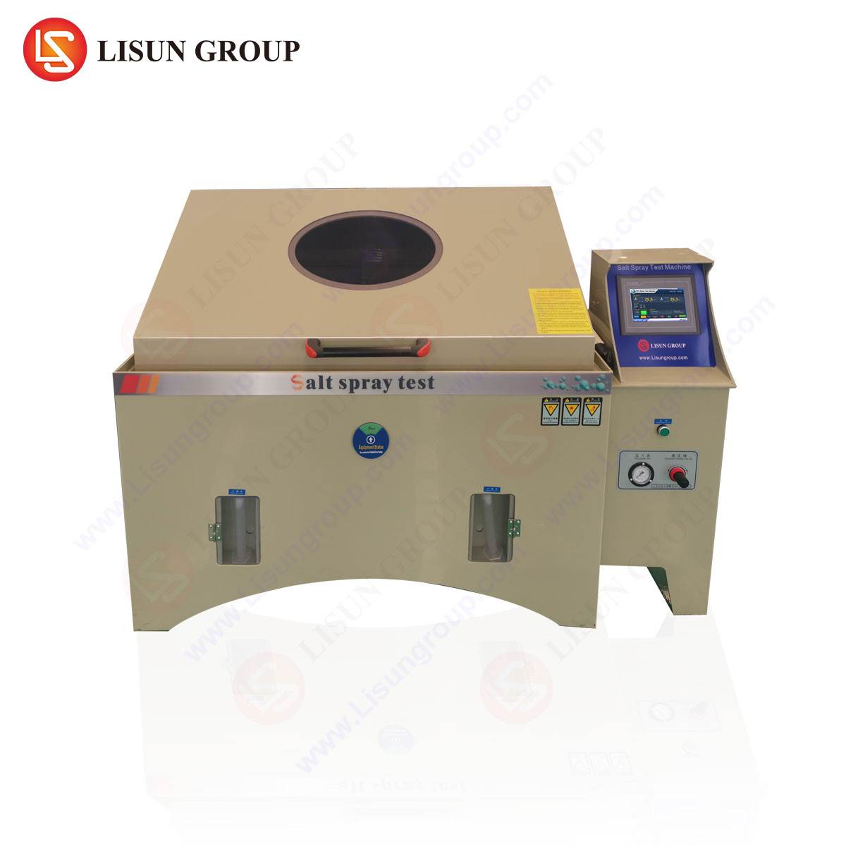
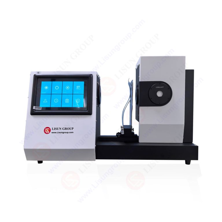
Case Study: The LISUN SC-015 Dust Sand Test Chamber in Application
To contextualize these considerations, an examination of a specific implementation is instructive. The LISUN SC-015 Dust Sand Test Chamber is engineered to address the precise requirements outlined in the aforementioned framework, serving as a relevant case study in applied design.
Specifications and Testing Principle: The SC-015 is designed primarily for IEC 60529 IP5X and IP6X testing. Its working volume is strategically sized (typically 0.5 to 1 cubic meter variants) to accommodate a wide range of products while maintaining efficient dust consumption and uniformity. The chamber employs a closed-loop vertical airflow system. A bottom-mounted blower draws air through a high-efficiency filter, then directs it upwards through a diffuser plate into the test zone, creating a controlled vertical laminar flow. The test dust is stored in a separate, sealed reservoir and is injected into the airstream via a precision cyclone separator and fluidized bed system. This ensures the dust is de-agglomerated, dry, and introduced at a consistent rate, maintaining the required concentration. After passing over the UUT, the dust-laden air is drawn down through a return duct, where coarse particles settle, and finer particles are filtered before recirculation, preserving the specified particle size distribution.
Industry Use Cases and Configurations:
- Electrical Components & Automotive Electronics: Used to validate the sealing integrity of connectors, sensors, switches, and ECUs against fine road dust, ensuring reliability in engine bays and underbody applications.
- Lighting Fixtures & Outdoor Telecommunications Equipment: Critical for testing IP-rated streetlights, floodlights, and base station antennas, where dust ingress can cause lumen depreciation, overheating, or electrical failure.
- Medical Devices & Aerospace Components: For testing portable diagnostic equipment, panel seals on avionics bays, and other devices where particulate contamination could lead to catastrophic functional or safety failures.
- Industrial Control Systems & Office Equipment: Validates the robustness of PLC housings, servo drives, and printers/copiers intended for use in manufacturing or industrial office environments.
Competitive Advantages in Design: The SC-015 exemplifies several selection criteria. Its use of 304 stainless steel interior and abrasion-resistant silicone door gaskets addresses durability. The integrated digital airflow meter and dust concentration sampling ports speak to instrumentation fidelity. Its control system allows for programmable test cycles (dust-on, settling, off periods) with real-time logging, supporting audit readiness. Furthermore, LISUN typically provides a full validation report with each unit, demonstrating compliance with the spatial uniformity requirements of the target standards.
Financial Analysis: Total Cost of Ownership vs. Initial Purchase Price
The procurement decision must be evaluated through the lens of Total Cost of Ownership (TCO). A lower initial purchase price can be illusory if it correlates with higher long-term costs. TCO factors include:
- Energy Consumption: Efficiency of the blower motor and heating/cooling systems.
- Dust Consumption: A well-sealed, efficient recirculation system drastically reduces annual dust powder costs.
- Maintenance Downtime: Robust construction and accessible components reduce frequency and duration of maintenance.
- Calibration and Service: Cost and availability of certified calibration services.
- Test Failure Risk: A non-compliant chamber can lead to false positives (passing faulty products) or false negatives (failing good products), both of which carry immense costs in recalls, rework, or lost market opportunity.
Investing in a technically superior chamber from a reputable manufacturer often yields a significantly lower TCO over a 10-year horizon, despite a higher initial capital outlay.
Conclusion
Selecting a dust chamber manufacturer is a multidisciplinary exercise in quality engineering, standards compliance, and strategic procurement. It requires moving beyond brochure specifications to a deep assessment of design philosophy, validation rigor, material science, and post-sale support. By applying the structured framework of technical, operational, and financial considerations outlined herein, organizations can make an informed decision that safeguards the integrity of their product validation processes, ensures regulatory compliance, and contributes directly to enhanced product reliability and brand reputation in global markets.
FAQ Section
Q1: How often does the test dust need to be replaced in a chamber like the LISUN SC-015, and what factors affect this?
A: Dust replacement frequency is not time-based but usage-based. It depends on the total operational hours of the chamber under dust injection. Factors include the test concentration, chamber volume, and efficiency of the recirculation filtration system. Degradation of particle size distribution due to fracturing or moisture absorption also necessitates replacement. A common indicator is the inability to maintain the target concentration despite system adjustments. Regular gravimetric checks will determine the state of the dust.
Q2: Can a single dust chamber be used to test for both IP5X and IP6X compliance?
A: Yes, a well-designed chamber like the SC-015 is capable of performing both tests. The critical difference lies in the test procedure and evaluation. The chamber must be able to create the required dust cloud for both. For IP6X, the test is typically more prolonged, and the evaluation (often involving a vacuum draw-down test for internally powered devices or internal examination for non-powered enclosures) is stricter. The chamber itself provides the controlled environment; the standard dictates the test method applied within it.
Q3: For testing powered devices like operating servers or LED drivers during dust exposure, what special chamber features are required?
A: Key features include:
- Electrical Feed-Throughs: Sealed ports that allow power and signal cables to enter the chamber without compromising the seal.
- Functional Monitoring Capability: The ability to power the device and monitor its operational parameters (e.g., temperature, output voltage, data integrity) in real-time via the control system or external instruments.
- Load Compatibility: The chamber’s electrical infrastructure must safely support the UUT’s power requirements.
- Heat Dissipation Consideration: The chamber’s airflow and cooling system may need to account for the thermal load of the operating device to prevent unrealistic temperature rise.
Q4: What is the typical lead time for chamber validation and calibration after installation, and who performs it?
A: Initial validation is ideally performed by the manufacturer’s qualified engineers as part of the installation and commissioning process on-site, typically taking 1-2 days. This provides the crucial baseline report. Annual recalibration is a service offered by the manufacturer or accredited third-party metrology labs. Lead times for calibration services vary but should be scheduled weeks in advance. On-site calibration is preferred to avoid chamber disassembly and shipping.