


Ensuring Electrical Safety and Compliance: The Role of Advanced Socket Testers in Modern Verification Protocols
The global proliferation of electrical devices, coupled with increasingly stringent international safety regulations, has elevated the importance of reliable electrical installation verification. Among the most critical points of interface between electrical infrastructure and end-user equipment are plugs and sockets. Ensuring these components are wired correctly and function within defined safety parameters is a non-negotiable prerequisite for preventing electrical hazards, equipment damage, and ensuring regulatory compliance. This technical analysis examines the sophisticated methodologies employed in socket testing, with a specific focus on solutions engineered for adherence to the rigorous VDE (Verband der Elektrotechnik, Elektronik und Informationstechnik) standards, a benchmark for electrical safety primarily in the DACH region (Germany, Austria, Switzerland) and influential worldwide.
The Imperative of VDE Standard Compliance in Socket Safety
VDE standards, such as VDE 0620 for plugs and socket-outlets and VDE 0100 for the erection of low-voltage installations, establish exhaustive requirements for construction, testing, and performance. Compliance is not merely a legal formality but a scientifically-grounded framework for hazard mitigation. These standards address risks including electric shock from incorrect wiring, fire hazards due to poor connections or insulation failures, and equipment malfunction from voltage anomalies. A socket tester designed for VDE compliance must therefore perform verification beyond simple continuity checks. It must assess the installation against a comprehensive set of criteria defined by the standard, including but not limited to: correct phase (L), neutral (N), and protective earth (PE) connection; presence and correct polarity of voltage; earth loop impedance (Zs) to ensure protective devices operate within stipulated times; and the integrity of the residual-current device (RCD). The testing instrument itself must be designed and calibrated to provide measurements with the accuracy and reliability demanded by the standard, ensuring that a “pass” indication is a definitive statement of safety.
Architectural Principles of a Modern VDE-Compliant Socket Tester
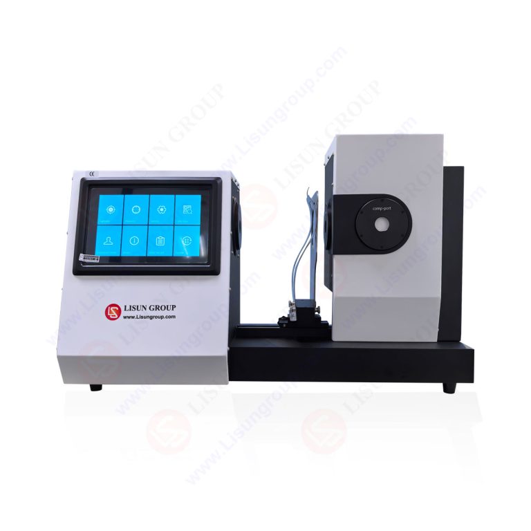
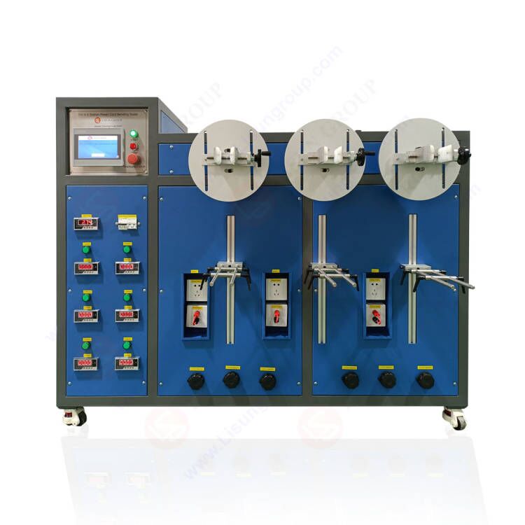
Contemporary socket testers transcend the functionality of basic neon-lamp indicators. A unit engineered for professional verification, such as the LISUN Gauges for Plugs and Sockets series, embodies an integrated measurement system. Its operational principle is based on controlled, safe load application and precision measurement circuitry. Upon insertion into a socket-outlet, the device initiates a sequenced test protocol. It first verifies basic wiring correctness (L-N, L-PE, N-PE voltages). Crucially, for earth verification, it applies a calibrated load between Line and Earth, measuring the resultant voltage drop to calculate earth loop impedance. This is a fundamental advancement over simple continuity testers, as it evaluates the functional performance of the earth path under a simulated fault condition. Similarly, for RCD testing, the device generates a calibrated leakage current (typically at ½ IΔn and IΔn, e.g., 15mA and 30mA for a 30mA RCD) and measures the tripping time. The internal microprocessor compares all measured values—impedance, trip time, voltage, frequency—against pre-programmed thresholds derived directly from VDE 0100 and related standards. The results are then presented via a clear visual display, often combining an LCD with LED indicators for immediate fault diagnosis.
Technical Specifications and Functional Capabilities of the LISUN Gauges Series
The LISUN Gauges for Plugs and Sockets product line exemplifies the technical requirements for a comprehensive compliance tool. Key specifications are defined to meet the exacting demands of field and laboratory testing.
Measurement Parameters and Accuracy:
- Socket Wiring Verification: Detects all common wiring faults (open circuit, swapped conductors, lost neutral, etc.) for various socket types (e.g., Schuko Type F, CEE 7/7).
- Voltage Measurement: Range typically 90V – 280V AC, with an accuracy of ±1.5% ±5 digits, ensuring precise assessment of supply voltage.
- Earth Loop Impedance (Zs): Measurement range from 0.10 Ω to 199.9 Ω, with a resolution of 0.01 Ω at lower ranges. Accuracy is critical here, often specified at ±(2% + 3 digits) to ensure reliable verification of circuit protection.
- RCD Trip Time and Current Testing: Tests both Type AC and Type A RCDs at standard test currents (IΔn/2, IΔn, 5IΔn). Measures trip times from <10ms to 2000ms with an accuracy of ±(2% + 3 digits). Some advanced models may include ramp testing for determining actual tripping current.
- Frequency and Polarity: Verifies supply frequency (e.g., 50/60 Hz) and correct polarity.
Safety and Build Specifications:
- Protection Category: Housed in a durable, insulated casing with a protection rating of at least IP40 for general use, and often higher for specialist environments.
- Fuse Protection: Internally protected by high-breaking capacity (HBC) fuses to safeguard the instrument and user during fault condition testing.
- Calibration: Traceable to national standards, a mandatory requirement for any measurement device used in compliance auditing.
Data Presentation and Connectivity:
- A multi-segment LCD displays numerical values (impedance, voltage, trip time) simultaneously with symbolic fault indicators.
- Professional-grade models may feature Bluetooth connectivity, allowing for the wireless transfer of test results to a smartphone or tablet app. This enables the creation of digital test reports, asset logging, and long-term data trending, which is invaluable for preventive maintenance regimes.
Industry Applications and Use-Case Scenarios
The application of a VDE-focused socket tester spans multiple industries where electrical safety and documentation are paramount.
Electrical Contracting and Installation: Prior to handing over a new or refurbished installation, electricians must provide verification of compliance. Using a device like the LISUN tester allows for rapid, on-site validation of every socket-outlet against VDE 0100-600. The ability to measure actual earth loop impedance at the point of use provides concrete evidence that overcurrent protective devices will operate within the required disconnection times, a core tenet of the standard.
Manufacturing and Industrial Facility Maintenance: In plants with heavy machinery, CNC equipment, and sensitive control systems, incorrect socket wiring can lead to catastrophic equipment failure or production downtime. Scheduled preventive maintenance routines include socket testing to ensure power quality and safety integrity. The RCD testing capability is particularly vital in areas with wet processes or where portable equipment is used, as mandated by VDE 0100-410 for additional protection.
Quality Assurance in Appliance Manufacturing: Manufacturers of electrical appliances must test their production-line test stations and end-of-line test sockets to ensure they are providing correct and safe power for product testing. A miswired test station could lead to a faulty appliance passing QA checks or, conversely, a functional appliance being rejected.
Hotel, Hospitality, and Real Estate Management: For safety and liability reasons, periodic testing of socket-outlets in guest rooms and rental properties is essential. A simple, robust tester allows facility staff to quickly verify the safety of installations, documenting checks for audit purposes.
Comparative Advantages in a Specialized Market
Within the landscape of electrical test equipment, devices engineered for specific standard compliance offer distinct advantages over generic testers. The LISUN Gauges series demonstrates several such differential factors.
Algorithmic Precision for Standard-Specific Thresholds: The device’s firmware is programmed with the exact permissible limits for impedance and trip times as defined by VDE 0100. It automatically applies the relevant thresholds based on the detected socket type and measured voltage, removing interpretation errors from the user.
Integrated, Safe Testing Workflow: By combining wiring, impedance, and RCD tests in one sequential, automated operation, the tester reduces procedural errors and minimizes the time the user is exposed to live circuits. The load application for impedance testing is carefully controlled and brief.
Data Integrity and Audit Trail: The move towards digital record-keeping is supported by models with data logging. This creates an immutable, time-stamped record of compliance tests, which is a powerful tool for demonstrating due diligence to inspectors, insurers, and clients.
Durability and Ergonomic Design: Built for daily professional use, the housing, probe pins, and internal components are designed to withstand mechanical stress. Clear, intuitive interfaces reduce training time and prevent misoperation.
The Evolution of Testing: From Verification to Data-Driven Safety Management
The future of electrical safety testing lies in the integration of measurement data into broader facility management systems. The next generation of socket testers will not only diagnose faults but also predict them. By analyzing trends in earth loop impedance over time—a potential indicator of corrosion or loosening connections—maintenance can be scheduled proactively. The role of the socket tester thus evolves from a simple verification tool to a critical node in the Internet of Things (IoT) for electrical safety, providing the empirical data necessary for predictive analytics and intelligent safety management, all while maintaining the foundational requirement of strict adherence to evolving standards like those published by VDE.
FAQ: LISUN Socket Testers and VDE Compliance Testing
Q1: Can the LISUN Socket Tester be used to verify compliance with standards other than VDE, such as IEC or UK BS 7671?
A1: Yes, while optimized for VDE thresholds, the core measurement principles (wiring, impedance, RCD) are universal. Many models allow the user to select the applicable standard from a menu, which adjusts the pass/fail criteria accordingly. The device measures absolute values (Ohms, seconds, Volts), which can be evaluated against any regional standard’s limits, though the pre-programmed VDE algorithms provide the most direct compliance check for that framework.
Q2: How often should a professional socket tester like the LISUN Gauges model be calibrated, and what does calibration entail?
A2: For instruments used in formal compliance verification, annual calibration by an accredited laboratory is recommended. Calibration involves comparing the tester’s measurements against a reference standard with a higher order of accuracy across its entire measurement range (voltage, impedance, time). The instrument is then adjusted to correct any deviations, and a certificate of calibration is issued, providing traceability to national standards.
Q3: What does a “PE Fault” or high earth loop impedance reading indicate, and what are the typical causes?
A3: A “PE Fault” or impedance reading above the permissible limit indicates an inadequate protective earth connection. This is a serious safety hazard as it could prevent a circuit breaker or fuse from operating quickly during a fault. Common causes include a loose or corroded earth terminal in the socket or distribution board, a broken earth conductor, or an excessively long circuit run with undersized cabling. Further investigation with a dedicated earth tester may be required to locate the fault.
Q4: Is it safe to use the socket tester on a live circuit? What protections are in place for the user?
A4: Yes, these testers are designed for safe use on energized socket-outlets up to their rated voltage (e.g., 230V AC). Key safety protections include: high-grade insulated housing; internal fuse protection to isolate faults; and test sequences that apply loads only briefly. However, users must always follow basic electrical safety protocols, such as visually inspecting the tester and socket for damage before use.
Q5: The tester indicates correct wiring but fails the RCD test. What might be the issue?
A5: Correct wiring does not guarantee functional RCD operation. An RCD test failure (typically a no-trip or slow-trip result) points to a faulty or degraded RCD device itself. The internal mechanism may be mechanically seized, or its electronic sensing circuitry may have failed. The RCD should be de-energized, replaced by a qualified electrician, and the new unit retested. It is also prudent to check that the load side wiring does not have existing, persistent earth leakage that could mask the test signal.