


Evaluating Fire Hazard Resistance with Needle Flame Testing
The proliferation of electrical and electronic equipment across global markets has intensified the focus on product safety and reliability. Among the most critical risks associated with these devices is the potential for fire ignition and propagation due to electrical faults, component failure, or overheating. To mitigate these hazards, international safety standards mandate rigorous testing to simulate and assess the flammability of materials and sub-assemblies. The needle flame test stands as a fundamental procedure within this compliance framework, designed to evaluate the resistance of a material to a small, localized flame, simulating conditions such as a fault within an overloaded transformer or a failing capacitor.
Principles of the Needle Flame Test Simulation
The core objective of the needle flame test is to subject a test specimen to a controlled, small-scale flame impingement to observe its reaction. The test is not intended to replicate a large conflagration but rather to model a specific, high-probability ignition source: a low-energy flame that may result from an electrical fault. The test flame is produced by a specially designed burner fed with a prescribed fuel, typically 99% purity propane, at a regulated flow rate. The burner tip, or “needle,” generates a nominal 1kW flame with a stable height, which is applied to the specimen for a predetermined period, usually 30 seconds. Following the application of the flame, the test apparatus is used to measure key parameters: the duration of any subsequent flaming or glowing combustion of the specimen, the extent of material damage (burned length), and whether any dripping of burning particles occurs that could ignite a secondary fire. The pass/fail criteria are strictly defined by the relevant standards, often based on the self-extinguishment time and the prevention of flame spread beyond specified limits.
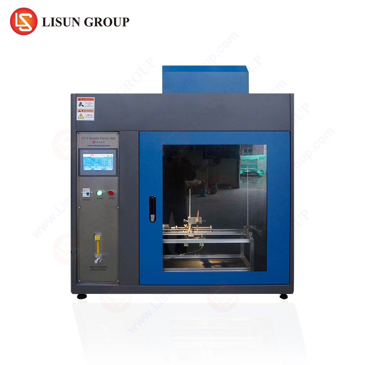
Architectural Configuration of the LISUN ZY-3 Test Chamber
The LISUN ZY-3 Needle Flame Test Chamber embodies a fully integrated system engineered for precision, repeatability, and operator safety. Its architectural design is a direct response to the stringent requirements of international standards such as IEC 60695-11-5, GB/T 5169.5, and others. The chamber’s primary enclosure is constructed from double-walled stainless steel, providing structural integrity and thermal isolation. A large, reinforced viewing window, often composed of tempered glass, allows for unobstructed observation of the test in progress, which is critical for accurate timing and behavioral analysis.
Internally, the chamber features a meticulously calibrated gas supply system, comprising a high-precision pressure regulator and flow meter to ensure a consistent and repeatable flame profile. The specimen staging area is designed for versatility, accommodating a wide range of product sizes and geometries through an adjustable mounting bracket. This bracket allows for precise positioning of the specimen relative to the burner needle in three-dimensional space, a critical factor for test reproducibility. The burner assembly itself is a key component, designed for easy ignition and stability, even in the presence of minor air currents within the test chamber. An integrated timing system, typically digital with millisecond accuracy, automatically controls the flame application duration and subsequently measures the after-flame and after-glow times. To ensure operational safety, the LISUN ZY-3 is equipped with an automatic gas shut-off valve and an exhaust system to remove combustion products, maintaining a safe testing environment.
Table 1: Key Specifications of the LISUN ZY-3 Needle Flame Test Chamber
| Parameter | Specification |
|---|---|
| Chamber Dimensions | Typically > 0.5 m³ volume (exact dimensions vary by model) |
| Burner Type | Standardized needle flame burner |
| Fuel Gas | 95% minimum purity Propane |
| Gas Pressure Regulation | Integrated high-precision pressure regulator |
| Flame Application Time | 0 to 999.9 seconds (digital timer, adjustable) |
| After-Flame/Glow Timer | 0 to 999.9 seconds (automatic, with stop function) |
| Specimen Mounting | Multi-angle, adjustable bracket |
| Viewing Window | Tempered glass with protective shield |
| Standards Compliance | IEC 60695-11-5, GB/T 5169.5, UL 746C, and others |
| Safety Features | Automatic gas shut-off, combustion gas exhaust port |
Calibration and Flame Verification Protocols
The validity of any needle flame test is entirely contingent upon the precise calibration of the test flame. The LISUN ZY-3 incorporates procedures and, in some models, integrated fixtures to facilitate this critical verification step. Calibration is performed using a dedicated copper block calorimeter specified in the standards. The burner is positioned at a defined angle and distance from the copper block, and the flame is applied for a set period, typically (23.5 ±1.0) seconds. The subsequent temperature rise of the copper block, measured by a thermocouple, is used to calculate the nominal calorific value of the flame, which must fall within a tight tolerance to confirm a 1kW output. This process verifies that the gas flow rate, pressure, and burner geometry are correctly configured to produce the standardized thermal insult. Regular calibration, performed before a test series or at defined intervals, is non-negotiable for maintaining the integrity of test data and ensuring that results are comparable across different laboratories and testing periods.
Application Spectrum Across Industrial Sectors
The utility of the needle flame test spans a vast array of industries where electrical safety is paramount. Its application is crucial for qualifying materials and components that could be sources of ignition in fault conditions.
- Electrical and Electronic Equipment & Household Appliances: Circuit boards, relay housings, wire insulation, and internal structural supports within devices like washing machines, refrigerators, and air conditioners are tested to ensure that a minor electrical arc does not lead to a cabinet fire.
- Automotive Electronics: With the increasing electrification of vehicles, components such as battery management system (BMS) enclosures, wire harness conduits, and sensor connectors are subjected to needle flame testing to prevent fires originating from the high-voltage electrical system.
- Lighting Fixtures: Particularly for LED drivers and plastic housings of luminaires, the test assesses the risk of flame propagation from a overheated or short-circuited component within the sealed fixture.
- Industrial Control Systems & Telecommunications Equipment: Plastic enclosures for programmable logic controllers (PLCs), server racks, and network switches are evaluated to contain any internal fault, protecting critical infrastructure.
- Medical Devices: For equipment like patient monitors and infusion pumps, the use of flame-retardant materials, verified through this test, is critical in oxygen-rich environments to prevent catastrophic outcomes.
- Aerospace and Aviation Components: The stringent safety requirements in aviation demand that nearly all non-metallic materials used in cabin interiors and electronic bay components demonstrate high resistance to ignition from small flames.
- Electrical Components: Directly relevant to items like switches, sockets, and connectors, which are frequent points of failure and potential ignition sources.
- Cable and Wiring Systems: Insulation and jacketing materials are tested to ensure they do not propagate flame along their length, a key factor in containing fires within cable trays and conduits.
Comparative Analysis with Alternative Flammability Assessments
While the needle flame test is a specific tool, it exists within a broader ecosystem of flammability assessments. Its primary differentiator is the simulation of a low-energy, localized ignition source. The Glow-Wire Test (IEC 60695-2-10), for instance, simulates thermal stresses caused by overheating components (e.g., a faulty resistor) by applying a glowing element rather than a flame. The Horizontal/Vertical Flame Test (UL 94) is more focused on the material’s inherent burning characteristics—its burning rate and drippiness—when subjected to a larger Bunsen-burner-type flame. The needle flame test occupies a unique niche: it is less severe than some large-scale flame tests but more directly simulates a specific, common fault scenario (a small flame) than the glow-wire test. Its value lies in its targeted applicability, providing data that is highly relevant for assessing fire risks from electrical faults that produce small, initial flames.
Operational Procedure and Data Interpretation
A standardized operational sequence is critical for reproducibility. The procedure for the LISUN ZY-3 typically involves: 1) Verifying chamber cleanliness and gas supply; 2) Mounting the specimen on the adjustable bracket according to the product standard’s requirements; 3) Precisely positioning the burner at the specified angle and distance (e.g., 45°) from the test point; 4) Igniting the burner and allowing the flame to stabilize; 5) Automatically applying the flame for the test duration (e.g., 30s); 6) Upon burner retraction, automatically starting the timer to record after-flame time (t₁) and after-glow time (t₂); 7) After the specimen has cooled, measuring the extent of charring or burned length from a fixed reference point.
Interpretation of results is strictly governed by the applicable standard. For many components, a primary criterion is that the after-flame time (t₁) does not exceed a specified limit, often 30 seconds. Furthermore, the test is typically failed if flaming or glowing reaches a boundary marker, if burning droplets ignite a surgical cotton indicator placed below the specimen, or if the burned length exceeds a defined threshold. The LISUN ZY-3’s precise timing and measurement aids provide the quantitative data necessary for this objective assessment.
Strategic Advantages of the LISUN ZY-3 Implementation
The deployment of the LISUN ZY-3 Needle Flame Test Chamber offers several distinct strategic advantages for quality assurance and R&D laboratories. Its design prioritizes measurement precision, achieved through its calibrated gas flow system and robust burner, which directly translates to high test repeatability and low inter-laboratory variation. The enhanced operational safety afforded by the sealed chamber, automatic gas shut-off, and exhaust system mitigates risk for technicians and protects the laboratory environment. Furthermore, its procedural efficiency is notable; the integrated digital timers, adjustable specimen holder, and clear viewing window streamline the testing workflow, reducing set-up time and minimizing potential for operator error. Finally, its comprehensive standards compliance ensures that test results are recognized and valid for achieving certification from major international bodies, a non-negotiable requirement for global market access.
Frequently Asked Questions (FAQ)
Q1: How frequently should the LISUN ZY-3 Needle Flame Test Chamber be calibrated?
Calibration frequency is dictated by usage intensity and the requirements of the laboratory’s quality system (e.g., ISO/IEC 17025). A common practice is to perform a full flame verification using the copper block method before commencing a new test series or at least once per week during active use. After any maintenance on the gas system or burner, calibration is mandatory.
Q2: Can the LISUN ZY-3 test irregularly shaped components, such as a molded connector?
Yes. The adjustable specimen mounting bracket is specifically designed for this purpose. It allows the technician to position the component so that the specific area of interest (e.g., a thin wall section or a terminal base) is correctly oriented and located relative to the test flame, as prescribed by the relevant product standard.
Q3: What is the significance of the surgical cotton indicator placed beneath the test specimen?
The cotton indicator is a critical part of the safety assessment. Its ignition by burning droplets or particles falling from the specimen constitutes a test failure. This simulates a real-world scenario where a small ignition from a faulty component could fall onto a readily ignitable material (e.g., dust, paper, textiles) below it, thereby starting a secondary fire.
Q4: Beyond the standard 30-second flame application, are other durations used in testing?
While 30 seconds is a common duration specified in many standards, the test procedure can be tailored. Some product-specific standards may require a shorter (e.g., 10s) or longer (e.g., 120s) flame application time to simulate a particular fault condition more accurately. The LISUN ZY-3’s digital timer is programmable to accommodate these variations.