


Needle Flame Test Temperature Guide: A Technical Framework for Fire Hazard Assessment
The evaluation of fire hazards presented by materials and components within electrotechnical products constitutes a critical pillar of product safety engineering. Among the standardized methodologies for assessing resistance to ignition from small sources, the needle flame test, as defined in standards such as IEC 60695-11-5, provides a controlled and reproducible simulation of a small, localized flame. This technical guide examines the temperature dynamics inherent to the needle flame test, delineating its operational principles, the significance of its thermal profile, and its application across diverse industries. A comprehensive understanding of the temperature parameters is essential for accurate test execution, consistent interpretation of results, and the subsequent design of inherently safer products.
Thermodynamic Principles of the Standardized Needle Flame
The needle flame test employs a precisely defined flame generated by the combustion of butane gas flowing through a specified orifice. The core objective is not to replicate a specific real-world fire scenario, but to apply a consistent and measurable thermal insult for comparative assessment. The flame’s thermal characteristics are a function of its geometry, fuel chemistry, and aerodynamics. The standard stipulates a flame with a nominal height of 12 ± 1 mm, which corresponds to a controlled energy output. The temperature distribution within this flame is not uniform; it features a high-temperature reaction zone within the inner cone and a more diffuse, but still potent, plume.
The critical parameter is the temperature achieved at a defined reference point. According to the calibration procedure outlined in IEC 60695-11-5, a 0.5 mm diameter Type K thermocouple, positioned 12 mm above the burner tip, must register a temperature of 1000°C ± 50°C within 10 seconds of flame application. This 1000°C benchmark is the cornerstone of the test’s repeatability. It ensures that regardless of the specific test apparatus used, the thermal challenge presented to the specimen is standardized. The flame’s small size (approximately 2mm in diameter at its base) ensures the challenge is localized, testing a material’s propensity to resist ignition, self-extinguish, and limit the propagation of flame from a point source, rather than its behavior under a fully developed fire condition.
Instrumentation for Precision: The LISUN ZY-3 Needle Flame Test Apparatus
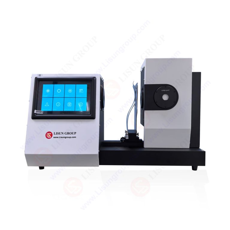
Achieving and maintaining the stringent temperature requirements of the needle flame test demands instrumentation of exceptional precision and stability. The LISUN ZY-3 Needle Flame Test Apparatus is engineered to meet these exacting demands, providing a fully integrated system for compliant testing. Its design incorporates features that directly govern the accuracy of the applied thermal profile.
The apparatus utilizes a high-precision mass flow controller to regulate butane gas supply, ensuring a consistent flame geometry and energy output. The burner needle is machined to exacting tolerances, guaranteeing the orifice diameter specified in the standard. The integrated thermocouple positioning system allows for micrometer-accurate placement of the calibration thermocouple at the mandated 12 mm height. Furthermore, the LISUN ZY-3 features a real-time temperature monitoring system, often with data logging capabilities, allowing technicians to verify that the 1000°C calibration point is not only reached but sustained stably throughout the test duration. This closed-loop control over gas flow, geometry, and temperature measurement is fundamental to generating a reproducible needle flame, making the apparatus a critical tool for accredited laboratories.
Key Specifications of the LISUN ZY-3 Apparatus:
- Test Flame: Conforms to IEC 60695-11-5, ISO 9773, and GB/T 5169.5.
- Flame Temperature: 1000°C ± 50°C (calibrated at 12mm height).
- Gas Flow Control: Digital mass flow controller for butane (99.5% purity).
- Timing Range: 0-999.9 seconds, with an accuracy of ±0.1s.
- Flame Application Time: Programmable from 0 to 999.9 seconds.
- Thermocouple: Standard Type K (NiCr-NiAl), 0.5mm diameter.
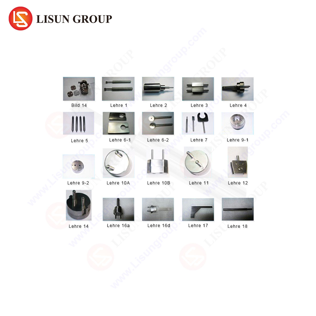
- Specimen Clamping: Adjustable, non-conductive clamp for various product forms.
- Safety Enclosure: Transparent, interlocked viewing chamber with fume extraction port.
Temperature Exposure and Material Response Metrics
The test procedure involves applying the calibrated needle flame to the specimen for a predetermined period (commonly 30 seconds, as per many end-product standards) and then removing it. The thermal profile experienced by the specimen is a complex interplay of radiant, conductive, and convective heat transfer. The immediate surface temperature at the point of impingement can approach the flame temperature, causing rapid pyrolysis of the material. The key metrics of material response are all temperature-dependent:
- Time to Ignition (TTI): The duration from initial flame application to sustained piloted ignition. A higher TTI indicates greater inherent resistance to the specific thermal flux.
- Flame Persistence (After-flame Time): The duration the specimen continues to flame after the test flame is removed. This measures self-extinguishing properties.
- Flame Spread and Burning Droplets: The extent of lateral flame propagation and the generation of ignited particulate matter, which are secondary ignition hazards.
- Post-Combustion Glow (After-glow Time): The duration of incandescence without flame, indicative of smoldering combustion.
The pass/fail criteria within an end-product standard (e.g., IEC 60950 for IT equipment, IEC 60335 for household appliances) typically set limits on after-flame time, the extent of burned area, and prohibit the emission of flaming droplets that ignite a surgical cotton indicator below. All these phenomena are direct consequences of the material’s thermal response to the 1000°C needle flame.
Industry-Specific Applications and Thermal Hazard Scenarios
The needle flame test is mandated across industries where electrical or electronic components could act as potential ignition sources due to fault conditions like overheating connections, arcing, or component failure.
- Household Appliances & Consumer Electronics: Tests internal wiring, motor insulation, PCB substrates, and external casings. A fault in a food processor’s motor winding or a power supply within a television could generate localized overheating, simulated by the needle flame.
- Automotive Electronics: Evaluates components in the passenger compartment and engine bay, such as connector bodies, sensor housings, and infotainment system parts. It addresses risks from short circuits in increasingly dense wiring harnesses.
- Lighting Fixtures: Applied to lamp holders, diffusers, and plastic housings for LED drivers. It assesses the risk from a faulty ballast or driver igniting adjacent materials.
- Industrial Control Systems & Telecommunications Equipment: Used for evaluating enclosures, wire ducting, and connector modules in control panels and server racks, where high component density increases fire propagation risk.
- Medical Devices: Critical for patient-connected and internally powered devices. Testing battery compartment materials, device housings, and internal insulations ensures a fault does not create a fire hazard in oxygen-rich or critical care environments.
- Aerospace and Aviation Components: While often subject to more severe tests, the needle flame test may be used for non-critical interior components, wire insulation, and accessory housings, focusing on minimizing fire load.
- Electrical Components & Cable Systems: A primary test for switches, sockets, terminal blocks, and small-gauge wiring insulation, simulating the effect of a poor connection generating sustained local heat.
Calibration Protocols and Temperature Verification
The integrity of any needle flame test result is wholly dependent on rigorous and regular calibration of the apparatus. The temperature verification is a two-stage process. First, the flame temperature calibration is performed: the standard thermocouple is positioned precisely 12 mm above the burner tip, the gas flow is adjusted until a stable 1000°C ± 50°C is achieved and maintained for a minimum period. The corresponding gas flow rate is documented as the standard setting.
Second, temporal accuracy calibration of the automatic timer controlling flame application is required. This ensures that a 30-second application is exactly that. Without this meticulous calibration, comparative testing between laboratories or over time becomes invalid. The LISUN ZY-3 facilitates this process with its digital controls and clear calibration points, ensuring traceability to national measurement standards.
Comparative Analysis with Alternative Flame Tests
The needle flame test occupies a specific niche in the hierarchy of fire tests. It is less severe than the glow-wire test (IEC 60695-2-10/11/12/13), which simulates thermal stresses from overheated or glowing elements (e.g., a faulty resistor) by pressing a heated wire onto the specimen. The glow-wire test typically operates at fixed temperatures (e.g., 550°C, 750°C, 850°C) and assesses ignition and spread of fire. Conversely, the needle flame is a flame-based test, providing a different ignition mechanism via a pilot flame.
It is also distinct from larger-scale horizontal or vertical flame tests (UL 94, IEC 60695-11-10) which classify materials based on burning rate and self-extinguishment under a larger (20mm) Bunsen burner flame. The needle flame’s utility lies in its simulation of a very small ignition source, making it particularly relevant for miniaturized components and dense electronic assemblies where a small fault is the postulated origin.
Data Interpretation and Integration into Safety Engineering
A “pass” in a needle flame test is not an absolute guarantee of safety but a quantitative measure of performance under a defined stress. Engineers use this data comparatively—to select one material over another, to validate a component from a new supplier, or to identify a need for design modification, such as adding a barrier, using a higher-grade polymer, or redesigning a heat sink.
The results feed into a broader fire hazard assessment, considering factors like the probability of the fault occurring, the potential energy available, the proximity of other fuels, and the presence of fire detection or suppression. The test provides a critical, standardized data point that allows for evidence-based risk mitigation in product design.
Frequently Asked Questions (FAQ)
Q1: Why is the calibration temperature set at 1000°C, and not another value?
The 1000°C value, established within IEC 60695-11-5, represents a severe but realistic temperature that can be generated by small electrical faults, such as a sustained arc or a severely overheated microscopic component. It provides a sufficiently high thermal challenge to differentiate between materials with poor and adequate resistance to small flames, ensuring a meaningful safety margin. The value is a consensus-based engineering severity level chosen for its reproducibility and discriminatory power.
Q2: How often should the LISUN ZY-3 Needle Flame Test Apparatus be calibrated?
Calibration frequency should follow the laboratory’s quality procedure, typically aligned with ISO/IEC 17025 accreditation requirements. It is generally recommended to perform a full temperature and timing calibration annually, or more frequently if the apparatus is used heavily or moved. A daily or pre-test verification of flame height and basic function is also considered best practice.
Q3: Can the needle flame test be performed on finished products, or only on material samples?
The test can be, and often is, performed on end products or representative sections thereof (“test specimens”). Many product safety standards (e.g., for power supplies, switches, or appliances) require testing the product in its most vulnerable configuration. This assesses the real-world interaction of flames with assemblies, seams, and material combinations, which can differ significantly from testing a homogeneous material plaque.
Q4: What is the significance of the surgical cotton indicator placed beneath the specimen?
The cotton wool layer simulates a readily ignitable material (like loose paper, dust, or flammable lint) that may be present in the product’s operating environment. The emission of burning droplets or particles that ignite the cotton constitutes a test failure. This addresses the secondary hazard where a component itself may not sustain a flame but can act as a wick to transfer fire to a surrounding fuel load.
Q5: How does the LISUN ZY-3 ensure consistent flame application angle and position?
The apparatus features a precision-engineered burner assembly mounted on a repeatable positioning mechanism. Many models include adjustable but lockable specimen holders and guides to ensure the mandated 45-degree application angle (or other specified angles) is maintained consistently across tests. This mechanical repeatability is as crucial as temperature stability in ensuring test rigor.