


A Technical Examination of Needle Flame Test Temperature Standards and Procedures for Material Fire Hazard Assessment
Introduction to Fire Hazard Evaluation via Needle Flame Testing
The proliferation of electrical and electronic equipment across diverse sectors—from automotive electronics and medical devices to household appliances and aerospace components—has necessitated the development of robust, standardized methods to evaluate the fire hazard potential of non-metallic materials. Among these methodologies, the needle flame test stands as a critical, small-scale fire simulation designed to assess the ignitability and flame-spread characteristics of materials when exposed to a small, localized flame source. This technical article provides a detailed exposition of the governing temperature standards, procedural protocols, and application-specific considerations for the needle flame test. The objective is to furnish engineers, quality assurance professionals, and regulatory compliance specialists with a comprehensive reference that underscores the scientific and practical dimensions of this essential safety evaluation.
Fundamental Principles and Thermal Dynamics of the Needle Flame
The needle flame test operates on the principle of simulating a fault condition within an electrotechnical product, such as an overheated component, a poor electrical connection, or an overloaded circuit element, which may generate a small, targeted flame. The test employs a standardized burner producing a nominal 1,000 ± 100 mm high flame with a specified thermal power output, typically calibrated using a 0.7 mm diameter copper wire melting point verification. The core thermal dynamic involves the impingement of this controlled flame onto a test specimen for a predetermined period (e.g., 30 ± 1 seconds). The subsequent observation period monitors for sustained combustion, flame spread, and the production of burning droplets or particles that could propagate fire to adjacent materials or structures.
The temperature profile of the needle flame is not defined by a single point measurement but by its total convective and radiative heat flux. Calibration is achieved through the verification of the burner’s thermal output by measuring the time required to melt a 0.7 mm diameter copper wire (melting point approximately 1084°C) positioned at a fixed distance from the burner tip. This indirect temperature calibration ensures reproducibility of the flame’s energy transfer characteristics, which is more relevant to real-world ignition scenarios than a simple gas temperature reading. The flame’s stability and geometry are maintained through precise control of gas flow rates (99% purity butane is standard) and burner needle orifice dimensions.
Governing Standards and Normative Temperature Calibration Protocols
The procedural and calibration requirements for the needle flame test are codified in several international and regional standards, which exhibit minor variations but share a common technical foundation. The primary standards include IEC 60695-11-5, GB/T 5169.5 (Chinese national standard), and other derivative norms such as UL 746A. These documents prescribe not only the test apparatus specifications but also the rigorous calibration routine essential for maintaining test validity.
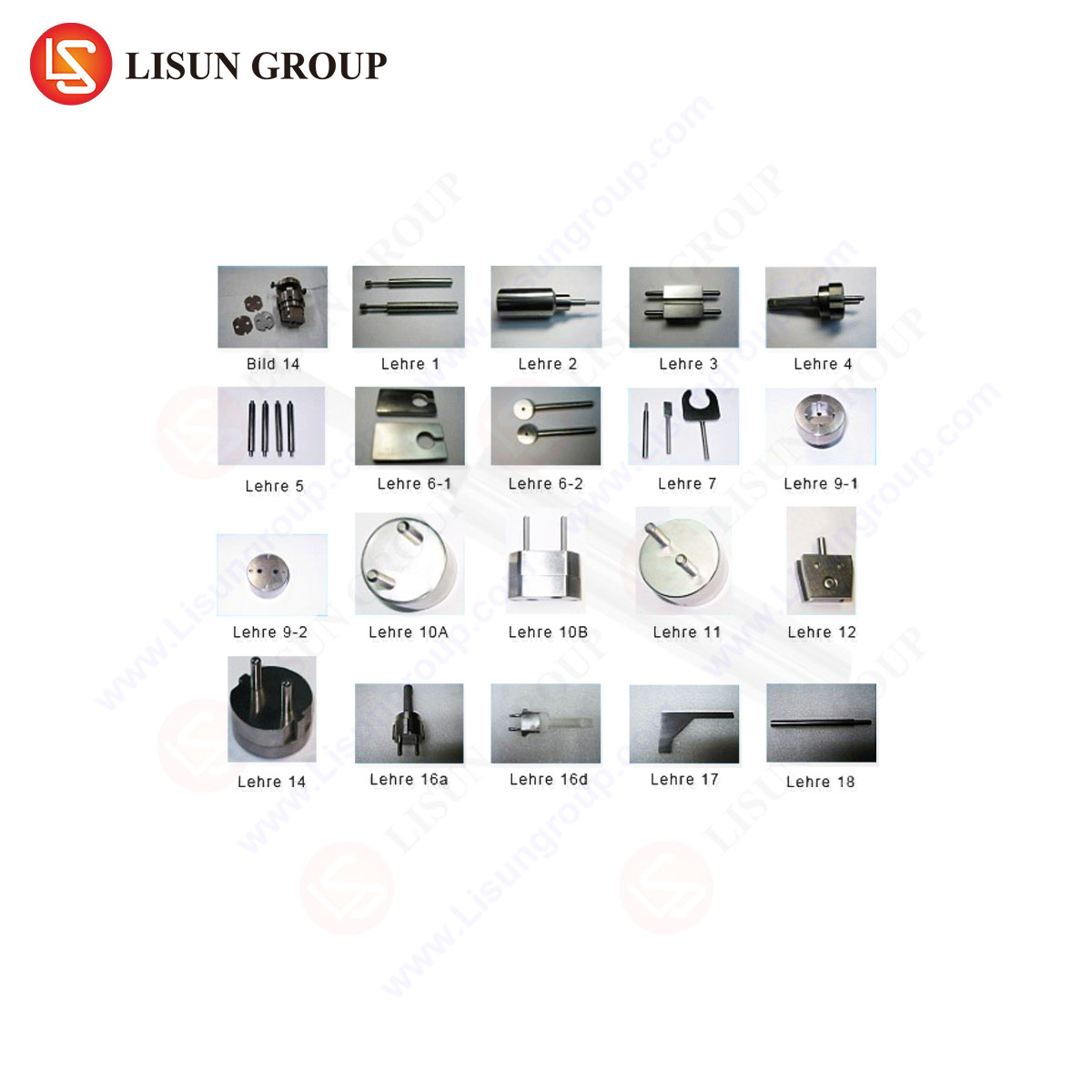
The central calibration procedure involves the copper wire melting verification. A standardized copper wire, 0.7 ± 0.05 mm in diameter and approximately 100 mm in length, is mounted horizontally on a dedicated calibration fixture. The needle flame is applied such that the tip of the inner blue cone contacts the wire at its midpoint. The time required for the wire to melt and separate, denoted as T_c, must fall within a strict window—typically between 4.0 and 6.0 seconds, as per IEC 60695-11-5. This time window correlates directly to the flame’s thermal power output. A melting time outside this range indicates an out-of-specification flame, necessitating adjustment of the gas flow rate or investigation of burner contamination. This calibration must be performed at regular intervals, typically at the start of each test session, to ensure ongoing compliance.
Apparatus Specifications: The LISUN ZY-3 Needle Flame Test Apparatus
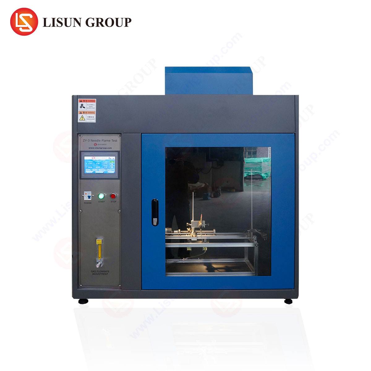
To execute the needle flame test with the requisite precision and repeatability, specialized apparatus is mandatory. The LISUN ZY-3 Needle Flame Test Apparatus represents a fully integrated system engineered to meet the exacting specifications of IEC 60695-11-5, GB/T 5169.5, and related standards. Its design incorporates features that address common procedural challenges, enhancing both operator safety and result reliability.
Key specifications of the LISUN ZY-3 include a digitally controlled, precision metering valve for butane gas flow, ensuring stable and repeatable flame generation. The apparatus features a fully adjustable test bench with three-dimensional specimen positioning (X, Y, Z axes), allowing for precise alignment of the flame relative to the test sample as mandated by specific product standards. An integrated electronic timer with automatic ignition and application sequencing removes operator timing variability. The unit is constructed with a stainless steel enclosure and a tempered glass observation window, providing durability and clear visibility while containing any potential debris. A built-exhaust system, often connected to external fume extraction, manages combustion products. The apparatus includes the mandatory calibration fixture and copper wires, streamlining the compliance workflow.
Procedural Execution: From Specimen Preparation to Result Interpretation
The test procedure is a sequence of defined steps, deviation from which can invalidate results. Initially, the test specimen, which may be a finished product, a sub-assembly, or a material sample, is conditioned in a standard atmospheric environment (e.g., 23 ± 2°C, 50 ± 5% relative humidity) for a minimum period, often 24 hours. The specimen is then mounted in its intended service position or as specified by the relevant end-product standard.
Following apparatus calibration (copper wire verification), the test flame is applied to the predetermined point on the specimen. The application angle (usually 45°) and distance are meticulously set. After the specified flame application time (e.g., 30 seconds), the burner is retracted. The critical observation period commences, during which the specimen is monitored for:
- Duration of after-flame (t_a): The time the specimen continues to flame after removal of the test flame.
- Duration of after-glow (t_g): The time the specimen continues to glow after cessation of flaming.
- Flame spread: Whether flames or glowing spread beyond a defined zone from the point of impingement.
- Burning droplets/particles: Whether any ignited material falls from the specimen and ignites a layer of surgical cotton located 200 ± 5 mm below the test point.
Pass/fail criteria are defined by the specific safety standard applicable to the end product. For instance, a common criterion for many electrical components is that after-flame time (t_a) does not exceed 30 seconds, and that burning droplets do not ignite the cotton indicator.
Industry-Specific Applications and Material Considerations
The needle flame test finds application across a vast spectrum of industries, each with unique material sets and risk profiles.
- Electrical Components & Household Appliances: Switches, sockets, connectors, and internal housings within appliances are tested to ensure a fault, such as a loose terminal, does not cause a self-sustaining fire.
- Automotive Electronics: With the increasing density of electronic control units (ECUs), wiring harnesses, and sensors in vehicles, materials used in these components are evaluated for resistance to ignition from short-circuit events.
- Lighting Fixtures: Particularly for LED drivers, plastic diffusers, and lamp housings, where heat buildup or electrical fault could pose an ignition risk.
- Medical Devices and Telecommunications Equipment: Enclosures and internal components of critical devices must demonstrate limited flame spread to ensure safety during operation and maintenance.
- Aerospace and Aviation Components: Non-metallic materials used in cabin interiors, control panels, and wiring systems are subject to stringent flame resistance requirements, with the needle flame test serving as a quality control check.
- Cable and Wiring Systems: While cables undergo larger-scale flame tests, material samples from jacketing and insulation may be screened using the needle flame method.
Material response is highly variable. Thermoplastics like polypropylene (PP) or ABS may melt and drip, potentially failing the cotton indicator test, while thermosets like phenolic resins may char but not sustain flame. Additives like flame retardants (e.g., halogenated compounds, phosphorus-based agents, or mineral fillers like aluminum trihydroxide) are specifically formulated to improve performance in such tests.
Comparative Advantages of Integrated Testing Systems
Utilizing a dedicated, integrated apparatus like the LISUN ZY-3 offers distinct advantages over improvised or partially assembled test setups. First, it guarantees geometric conformity to standard dimensions (burner orifice, calibration fixture distances), which is critical for reproducibility. Second, automated timing and ignition sequences eliminate a significant source of human error, enhancing the precision of the after-flame and after-glow measurements. Third, built-in safety features, such as gas leak detection, flame failure arrestors, and enclosed testing chambers, protect the operator and laboratory environment. Finally, integrated systems simplify audit and certification processes, as the apparatus itself is demonstrably designed to comply with normative specifications, reducing validation overhead for the testing laboratory.
Data Recording, Reporting, and Compliance Documentation
A complete test report is a legal and technical document that must encapsulate all parameters of the test execution. Essential data includes:
- Laboratory environmental conditions (temperature, humidity, pressure).
- Specimen details (material, supplier, thickness, color, conditioning).
- Calibration data (copper wire melting time T_c, gas flow rate).
- Test parameters (flame application angle, duration, impingement point).
- Test results (t_a, t_g, observation of flame spread, behavior of burning droplets, condition of cotton indicator).
- Photographic evidence of the specimen before, during, and after testing.
This documentation forms the basis for compliance declarations under frameworks such as the EU’s Low Voltage Directive, various UL standards, and CCC (China Compulsory Certification).
FAQ Section
Q1: How frequently must the copper wire calibration be performed on the LISUN ZY-3?
A1: Calibration is required at the beginning of each series of tests. If testing is conducted over multiple days, a new calibration is necessary at the start of each day’s testing session. Furthermore, calibration should be repeated if there is any suspicion of altered flame characteristics, such as after changing the gas supply cylinder or if the burner needle has been cleaned or replaced.
Q2: Can the LISUN ZY-3 be used for testing finished products, or is it only for material samples?
A2: The apparatus is designed to test both finished products and material samples. The three-dimensionally adjustable test bench allows for the secure mounting of variously sized and shaped end-products, such as small appliance housings, electrical connectors, or switch assemblies, in accordance with the positioning requirements specified in the applicable end-product safety standard.
Q3: What is the significance of the surgical cotton layer placed beneath the test specimen?
A3: The surgical cotton simulates lightweight, easily ignitable materials (like dust, lint, or flammable debris) that may be present in the product’s operating environment. The ignition of this cotton by burning droplets or particles from the test specimen constitutes a test failure, as it indicates the potential for a small initial fire to propagate to surrounding materials.
Q4: Our product standard references IEC 60695-11-5. Is the LISUN ZY-3 suitable for compliance testing?
A4: Yes. The LISUN ZY-3 is explicitly designed and manufactured to meet all apparatus requirements detailed in IEC 60695-11-5, including burner dimensions, gas type, calibration fixture geometry, and flame verification procedures. It is therefore a fully suitable apparatus for conducting compliance testing against that standard.
Q5: What are the critical maintenance aspects for ensuring the long-term accuracy of the needle flame apparatus?
A5: Key maintenance tasks include: regular cleaning of the burner needle orifice to prevent clogging from soot or contaminants; periodic leak testing of the gas supply lines and connections; verification of the gas pressure regulator and flow metering system; and ensuring the integrity of the timing and control electronics through routine functional checks. A log of all maintenance and calibration events should be maintained.