


Establishing Combustion Resistance: A Technical Examination of Needle Flame Test Standards and Procedures
The proliferation of electrical and electronic equipment across diverse sectors has necessitated the development of rigorous safety standards to mitigate fire hazard risks. Among the suite of flammability assessments, the needle flame test stands as a critical, simulation-based evaluation designed to assess the resistance of materials and sub-assemblies to a small, localized flame. This technical article delineates the underlying principles, governing standards, procedural methodologies, and instrumental requirements for conducting compliant needle flame testing. The objective is to provide engineers, quality assurance professionals, and regulatory specialists with a comprehensive reference that bridges theoretical standards with practical application.
Fundamental Principles of the Needle Flame Simulation
The needle flame test is predicated on the simulation of a small ignition source, such as an overheated or failing electrical component, a faulty connection, or a malfunctioning printed circuit board track. Unlike larger-scale flame tests, it does not seek to engulf a sample in flame but rather to evaluate the propensity of a material to resist ignition, limit flame spread, and self-extinguish once the primary ignition source is removed. The test employs a standardized flame produced by a specified burner fed with a hydrocarbon gas, typically at a thermal output of approximately 45W. This controlled flame is applied to the test specimen for a predetermined duration. The post-ignition behavior—including duration of flaming, extent of material consumption, and production of burning droplets or particles—is meticulously observed and measured. The core principle is to replicate a realistic fault condition within an end-product, such as an overloaded switch in household appliances, a short-circuited capacitor in automotive electronics, or a failing transformer in telecommunications equipment, thereby providing a quantifiable metric for fire safety.
Governing International Standards and Compliance Benchmarks
Compliance with international safety standards is non-negotiable for market access. The needle flame test is codified within several key standards, each with nuanced requirements tailored to specific product families. The foundational standard is IEC 60695-11-5, which details the test apparatus, calibration procedures, and generic test methodology. This standard is frequently invoked by derivative product-specific standards.
IEC/EN 60335-1 (Household and similar electrical appliances) incorporates the needle flame test to evaluate non-metallic parts that may be exposed to thermal stress from electrical faults. IEC/EN 60950-1 (Information technology equipment) and its successor, IEC/EN 62368-1 (Audio/video, information and communication technology equipment), mandate the test for parts within a defined fire enclosure. IEC/EN 60598-1 (Luminaires) applies it to insulating materials and other parts in lighting fixtures. The automotive sector references ISO 20653 and various OEM specifications for testing components like control units and wiring harnesses. For medical electrical equipment, IEC/EN 60601-1 stipulates flammability requirements that may be verified via needle flame testing. Understanding the specific clauses, severity levels (e.g., flame application time of 10s, 30s, or 60s), and pass/fail criteria (often related to flame duration, burning droplet behavior, and damage length) within the applicable standard is paramount for conducting a valid assessment.
Anatomy of a Compliant Needle Flame Test Apparatus
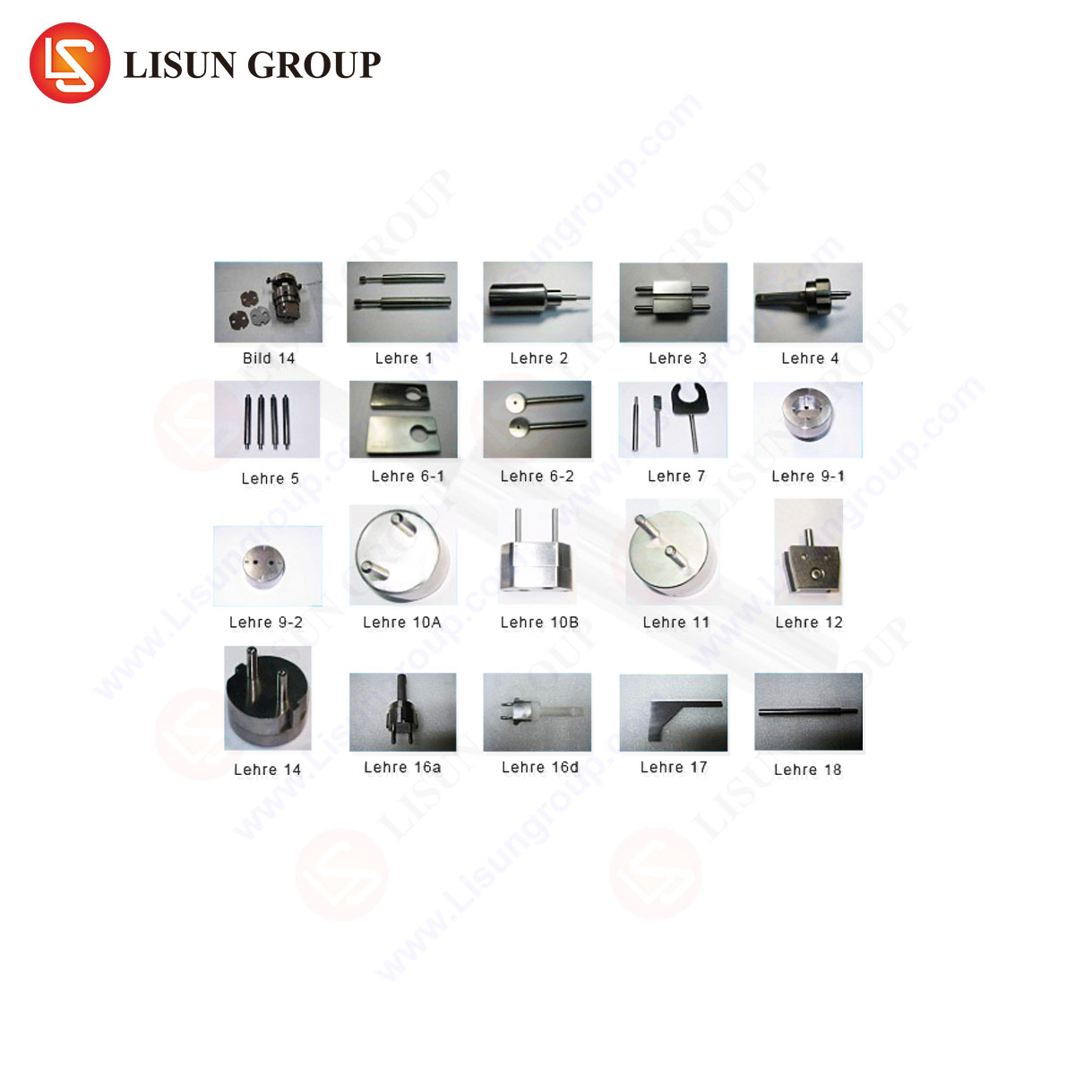
A standardized test apparatus is essential for reproducible and comparable results. The system comprises several integrated components. The core is a precision burner with a needle-like orifice, typically 0.5mm ± 0.1mm in diameter, mounted on a movable assembly. A high-precision gas supply system, incorporating a pressure regulator, flow meter, and needle valve, ensures a consistent flame of specified dimensions (e.g., 12mm ± 1mm height). A calibrated thermal probe, such as a type K thermocouple of defined mass, is used for periodic flame verification. The specimen holder must allow for positioning in various orientations as per the standard’s requirement. A controlled test chamber with a draught shield is necessary to eliminate ambient air disturbances. Underlying the assembly is a layer of preconditioned surgical cotton to assess the ignitability of falling burning particles. Timing devices with 0.1s accuracy and a linear scale for measuring burn extent complete the essential toolkit.
Operational Protocol: A Stepwise Testing Procedure
The testing procedure follows a strict sequence to ensure methodological integrity. It begins with specimen preparation, where samples are conditioned at a standard atmospheric temperature and humidity (e.g., 23°C ± 2°C and 50% ± 5% RH) for a minimum duration, often 24 hours. The apparatus calibration is then performed, verifying the gas flow rate and confirming the flame temperature meets the standard—commonly 1000°C ± 50°C when measured with a specified thermocouple placed at a set distance from the burner tip.
The test execution phase involves securely mounting the specimen in the prescribed orientation (e.g., vertical, horizontal, or at a 45° angle). The pre-adjusted flame is applied to the predetermined point on the specimen for the exact duration mandated by the product standard. Upon removal of the burner, observation and measurement commence immediately. Key parameters recorded include:
- t₁: The duration of flaming combustion after flame removal.
- t₂: The duration of glowing combustion after cessation of flaming.
- The maximum extent of damage, measured from the point of flame application.
- Whether any burning or glowing particles fall from the specimen and whether they ignite the surgical cotton wool indicator.
All observations are meticulously documented in the test report alongside specimen details, conditioning parameters, and a precise description of the flame application point.
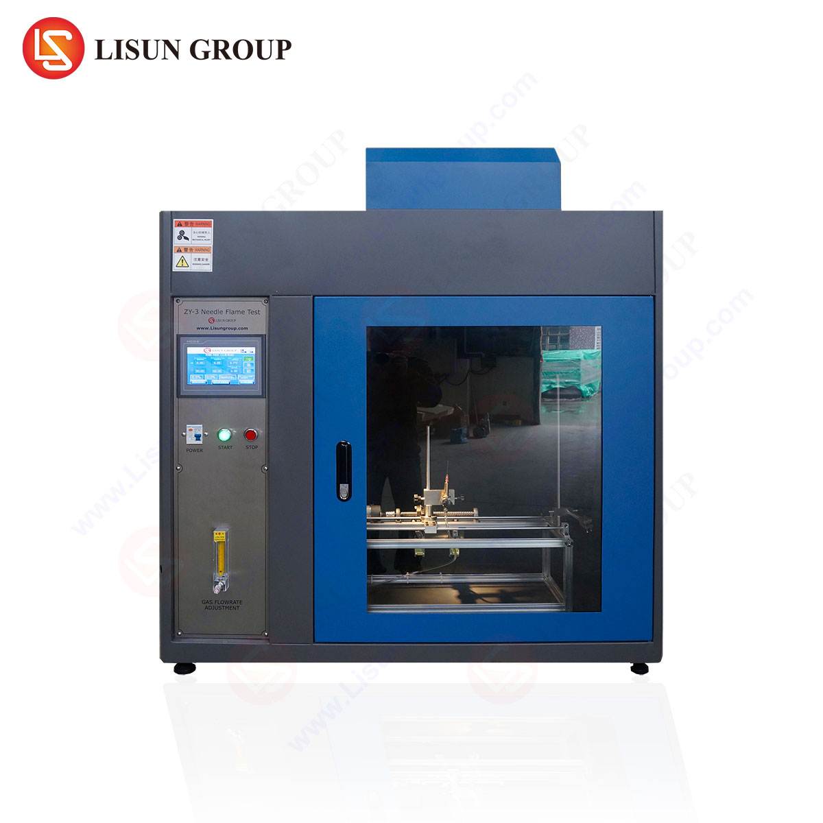
The LISUN ZY-3 Needle Flame Test Apparatus: Engineered for Precision and Compliance
The LISUN ZY-3 Needle Flame Test Apparatus embodies the integration of standard-mandated design with enhanced operational reliability for the modern testing laboratory. Engineered to meet the exacting requirements of IEC 60695-11-5, GB/T 5169.5, and related standards, it provides a fully integrated solution for conducting repeatable and auditable flammability assessments.
The apparatus features a stainless steel main body and draught-proof test chamber, ensuring long-term durability and a stable testing environment free from external air currents. Its precision-machined Bunsen burner with adjustable needle valve allows for fine-tuning to achieve the specified 12mm ± 1mm flame height. The integrated high-accuracy gas flow meter and pressure stabilization system guarantee consistent flame energy output across multiple tests and days of operation.
A key operational advantage of the ZY-3 is its motorized, automatic timing control system. The user sets the flame application time via a digital interface. Upon initiation, the burner advances, applies the flame for the exact duration, and retracts automatically, eliminating human timing error and enhancing operator safety. The specimen platform offers multi-axis adjustability, facilitating precise positioning of components as complex as an automotive connector, a medical device housing, or an industrial control relay in the required test orientation.
For calibration and verification, the system is complemented by a standardized copper block calorimeter and type K thermocouple, enabling routine confirmation that the flame temperature conforms to the 1000°C ± 50°C benchmark. This closed-loop verification is critical for maintaining the integrity of the quality assurance process in industries such as aerospace component manufacturing or medical device production, where traceability is essential.
Application Across Industrial Sectors: Specific Use Cases
The needle flame test finds critical application in vetting the fire safety of non-metallic parts across a vast industrial landscape.
- Electrical Components & Household Appliances: Testing terminal blocks, switch housings, socket faces, and internal supports in devices like washing machine control boards or electric kettle bases to ensure a faulty connection does not lead to cabinet fire.
- Automotive Electronics & Wiring Systems: Evaluating the resistance of connectors, wire insulation, sensor housings, and engine control unit (ECU) casings to localized overheating from short circuits or excessive current.
- Lighting Fixtures & Consumer Electronics: Assessing plastic diffusers, LED module housings, power supply enclosures within luminaires, and the internal chassis of televisions or gaming consoles.
- Industrial Control & Telecommunications: Verifying the flammability characteristics of relay covers, PLC housings, server fan shrouds, and router casings used in control panels and data centers.
- Medical Devices & Office Equipment: Ensuring that housings for patient monitors, infusion pumps, as well as printers and photocopiers, will not propagate a flame from an internal electrical fault.
Interpreting Test Results and Failure Mode Analysis
A “pass” or “fail” determination is made by comparing recorded data against the criteria in the applicable end-product standard. Common failure modes include excessive after-flame time (t₁), ignition of the indicator cotton by falling droplets, or the burn damage extending beyond a permitted length from the application point. Result interpretation is not merely binary; it feeds into failure mode analysis. For instance, a material that produces sustained flaming droplets may fail in an overhead installation (e.g., a lighting fixture) but might be acceptable in a vertically oriented control panel. Analysis of the burn pattern can inform material selection, component redesign (e.g., adding flame-retardant barriers or drip trays), or the implementation of protective circuitry. This analytical step transforms a compliance check into a valuable tool for product safety engineering.
Critical Factors Influencing Test Reproducibility
Achieving inter-laboratory reproducibility demands strict control over several variables. Specimen conditioning is primary; moisture content can significantly alter burning characteristics. Flame calibration must be performed daily or per test session using the standardized copper block method. Ambient conditions in the laboratory, particularly drafts, must be minimized by using the apparatus’ draught shield. The angle and position of flame impingement must be as specified, as a deviation of a few millimeters can alter heat flux. Finally, the condition and placement of the cotton indicator must be consistent, as its ignition is a key failure criterion. The automated features of instruments like the LISUN ZY-3 directly mitigate variability in timing and flame positioning.
Integration within a Broader Product Safety Strategy
The needle flame test should not be viewed in isolation. It is one element in a hierarchical flammability assessment strategy. It often follows material-level screening tests (e.g., Glow-Wire or UL 94) and precedes more severe product-level or simulation-based tests. Its role is specifically to bridge the gap between material properties and the response of a fabricated part or sub-assembly in a simulated fault scenario. A comprehensive safety strategy uses data from all these levels to inform design choices, select appropriate materials, and ultimately validate that the finished product—whether an aircraft in-seat power outlet or a life-saving ventilator—meets its required Fire Performance Index.
Frequently Asked Questions (FAQ)
Q1: What is the primary difference between the Needle Flame Test and the Glow-Wire Test?
A1: The fundamental difference lies in the ignition source. The Glow-Wire Test uses a heated element to simulate thermal stress from overloaded or glowing components, primarily assessing ignition resistance. The Needle Flame Test uses a small, open flame to simulate the impact of a small flaming source, assessing both ignition and flame spread/propagation behavior. They address different, though sometimes complementary, fault conditions.
Q2: For a new product, how do I determine the correct flame application time (e.g., 10s vs. 30s) to use?
A2: The test severity, including flame application time, is not chosen arbitrarily. It is prescribed by the specific end-product safety standard applicable to your device (e.g., IEC 60335-1 for appliances, IEC 62368-1 for IT equipment). You must consult the relevant clause within that standard, which will define the test conditions based on the component’s location, function, and the potential fire risk.
Q3: Can the LISUN ZY-3 apparatus be used for testing according to both IEC and UL standards?
A3: The LISUN ZY-3 is designed and calibrated to meet the specifications of IEC 60695-11-5 and related IEC-based standards (EN, GB/T). While the physical principle is similar, UL standards may have different apparatus dimensions, calibration protocols, or test procedures. It is crucial to verify that the apparatus specifications align perfectly with the normative references in your target standard before testing.
Q4: What are the most common causes of non-conformance during routine flame calibration?
A4: Drift in calibration is typically caused by a partially clogged burner orifice, fluctuations in inlet gas pressure, or an improperly adjusted gas flow rate. Regular maintenance, including cleaning the burner tip with appropriate tools and verifying the gas supply system’s stability, is essential. The use of a high-purity test gas, as specified in the standard, also prevents contamination.
Q5: How should falling droplets that solidify before reaching the cotton indicator be classified?
A5: This is a nuanced scenario addressed in standards. Typically, only droplets or particles that are still burning or glowing upon contact with the cotton are considered for ignition assessment. Droplets that solidify or extinguish in mid-air are generally noted in the report but do not constitute a failure based on the cotton ignition criterion alone. However, their presence may inform a broader engineering risk assessment.