


Technical Evaluation of Plug and Socket Safety: A Comprehensive Analysis of NF C 61-314 Figure C1 Gauge Compliance
Introduction to Dimensional Standardization in Electrical Accessories
The global proliferation of electrical devices necessitates a foundational commitment to safety and interoperability, principles enshrined within national and international standards. For plugs and socket-outlets, dimensional accuracy is not merely a matter of convenience but a critical safety parameter. Incorrect dimensions can lead to poor electrical contact, overheating, mechanical instability, and the dangerous possibility of partial insertion, where live pins remain accessible. The French standard NF C 61-314, which details the requirements for plugs and socket-outlets for household and similar purposes, provides the authoritative framework for the French market and influences regional norms. Within its annexes, Figure C1 presents a series of critical test gauges designed to verify the compliance of socket-outlets, ensuring they reject non-compliant plugs while safely accepting those meeting the standard. This technical treatise examines the principles and applications of NF C 61-314 Figure C1 gauge compliance, with a specific focus on the implementation of these tests using precision instrumentation such as the LISUN Gauges for Plugs and Sockets.
Deconstructing the NF C 61-314 Figure C1 Gauge Suite
Figure C1 of NF C 61-314 is not a singular tool but a defined set of dimensional gauges, each engineered to assess a specific safety-critical aspect of a socket-outlet’s geometry. These gauges are typically categorized into two primary functional groups: “go” gauges and “no-go” gauges. The “go” gauge, often representing the maximum permissible dimensions of a standardized plug, must insert into the socket-outlet with a specified force or under its own weight, verifying that compliant plugs will engage correctly. Conversely, the “no-go” gauges are designed to test rejection criteria. These gauges simulate plugs with undersized or oversized pins, incorrect pin angles, or other dimensional deviations that a safe socket must physically reject under test conditions.
A quintessential example is the gauge for testing protection against shock from accessible live parts. This “no-go” gauge, shaped to represent a plug with partially exposed conductive pins, is applied to the socket with a defined force. Compliance is achieved only if the gauge cannot be oriented in such a way that a standardized test finger, as per IEC 61032, can make contact with a live part through any aperture. Another critical gauge verifies the socket’s ability to prevent the insertion of a plug with incorrectly sized or spaced pins, a common fault in substandard or incompatible devices. The dimensional tolerances for these gauges are exceptionally tight, often within ±0.05 mm, reflecting the non-negotiable nature of the safety barrier they represent.
The Metrological Imperative for Calibrated Test Equipment
The efficacy of compliance testing hinges entirely on the precision and traceable accuracy of the gauges employed. Utilizing uncalibrated or generically fabricated gauges introduces unacceptable measurement uncertainty, potentially leading to false positives (accepting non-compliant sockets) or false negatives (rejecting safe ones). Therefore, test equipment must be manufactured from dimensionally stable materials, such as hardened steel or certified polymers, and must be regularly calibrated against national measurement standards. The LISUN Gauges for Plugs and Sockets are engineered to this metrological imperative. Constructed from high-grade, wear-resistant materials, each gauge in the LISUN suite is machined to the exacting dimensions stipulated in NF C 61-314 Figure C1, with full calibration certification provided to ensure traceability.
For instance, the LISUN gauge set includes precisely weighted and dimensioned “check gauges” for pin configuration. One gauge will verify that a socket accepts a plug with pins at the maximum allowable center distance, while another, slightly larger gauge will confirm that a plug with pins exceeding this distance cannot be inserted. The application of the specified test force—typically measured in Newtons—is also critical. LISUN equipment often incorporates integrated force measurement or is designed for use with calibrated push-pull force gauges, ensuring the mechanical test is performed as the standard prescribes, not merely as a visual check.
Operational Protocol for Gauge-Based Compliance Assessment
The testing protocol is a systematic, non-destructive procedure. A socket-outlet, mounted as intended for use, is subjected to the series of gauge tests in a controlled sequence. The process begins with visual inspection and dimensional verification of the socket face and contact apertures. Following this, the “go” gauge is applied. It must enter the socket smoothly, under its own weight or with a force not exceeding a value defined in the standard (e.g., 50 N), and achieve full seating. This confirms that the socket does not present undue mechanical resistance to a proper plug.
Subsequently, the “no-go” gauges are applied sequentially. Each must fail to be inserted or must only achieve partial insertion that does not create an electrical hazard. A common test involves applying a rotational moment to a partially inserted “no-go” gauge to ensure it cannot be manipulated to establish contact. The exact forces, angles, and durations for these manipulations are meticulously outlined in NF C 61-314. Data recording is essential; test reports must document the gauge used, the applied force, the observed result (pass/fail), and the environmental conditions. LISUN’s product documentation and support materials provide detailed testing workflows aligned with these protocols, reducing operator error and ensuring consistent, repeatable assessments.
Industry Applications and Regulatory Enforcement Contexts
Compliance with NF C 61-314 Figure C1 is mandatory for any socket-outlet placed on the French market. Consequently, the application of these gauge tests spans the entire product lifecycle. Manufacturers employ them during the design verification and type-testing phases to validate prototypes and production samples. Quality assurance departments integrate gauge checks into production line audits, performing statistical sampling to monitor manufacturing consistency. Furthermore, independent testing laboratories and certification bodies (such as those granting the NF mark or other CE marking evidence) use these gauges as part of their conformity assessment modules.
Beyond initial certification, market surveillance authorities utilize gauge testing for post-market monitoring. They can procure samples from distributors and retailers to verify ongoing compliance, ensuring that mass-produced items continue to meet the safety requirements long after the initial type-test certificate is issued. The portability and definitive nature of gauge tests make them ideal for such field inspections. The robustness of the LISUN gauge kits, often housed in protective cases with custom foam inserts, makes them particularly suited for both laboratory and field-use environments, maintaining their calibration integrity despite transport.
Technical Specifications of Advanced Gauge Systems
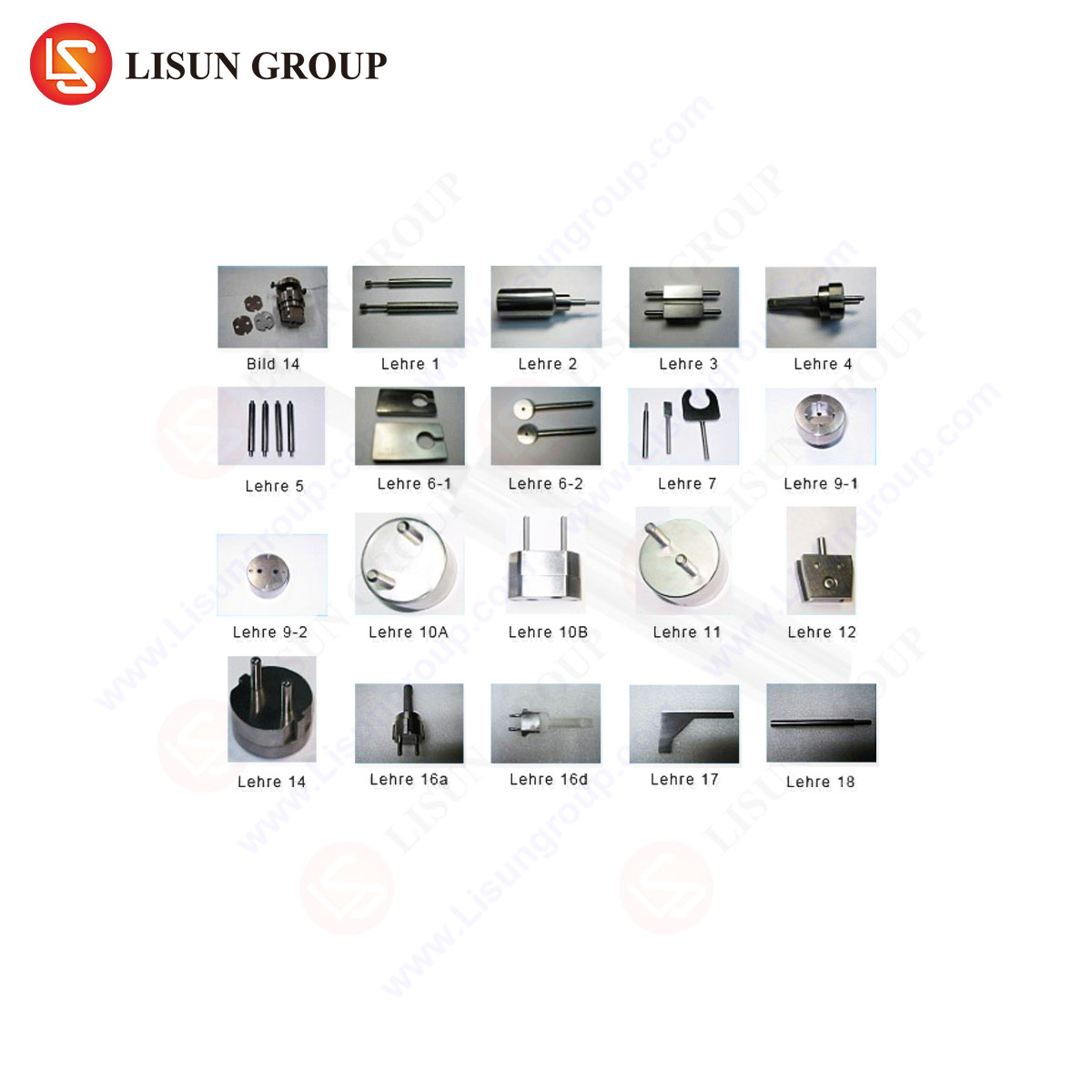
A modern gauge system transcends simple physical templates. Advanced kits, like those offered by LISUN, encompass a comprehensive array of tools. A typical set includes:
- Dimensional Gauges: For pin diameter, pin spacing (in all axes), and earth pin slot size.
- Safety Gauges: Including the standardized test finger and probes to verify shutters (where applicable) and protection against access to live parts.
- Force Application Tools: Calibrated weights or force gauges for applying the precise insertion and rotational forces mandated by the standard.
- Supplementary Fixtures: Mounting plates to secure socket-outlets in the intended use position during testing.
The materials specification is paramount. Gauges are manufactured from tool steel, hardened and ground, with a surface finish that prevents binding while ensuring accurate dimensions. Critical surfaces are often coated for corrosion resistance. Each gauge is individually serialized and accompanied by a calibration certificate from an accredited laboratory, referencing the specific clauses of NF C 61-314 Figure C1.
Comparative Analysis: The Advantages of Integrated Testing Solutions
While basic gauge sets are available, their value is contingent upon accuracy and usability. Integrated solutions provide distinct advantages. Firstly, they offer completeness, ensuring no required test from Figure C1 is omitted. Secondly, they provide traceability, with full calibration documentation that is essential for audit purposes. Thirdly, ergonomic design reduces operator fatigue and variability in test application.
The LISUN Gauges for Plugs and Sockets exemplify this integrated approach. The system is designed for logical workflow, with gauges clearly labeled for their specific test clause. The competitive advantage lies in this holistic design philosophy, which minimizes the risk of procedural error. Furthermore, LISUN often provides complementary support, such as detailed pictorial testing guides and access to technical expertise on the application of the standard, which is invaluable for laboratories handling multiple global specifications. This transforms the gauge set from a simple measurement tool into a comprehensive compliance assurance system.
Conclusion: The Role of Precision Verification in Consumer Safety
The gauges specified in NF C 61-314 Figure C1 serve as the physical arbiters of a critical safety interface. Their application represents a direct, unambiguous method for enforcing the dimensional requirements that prevent electrical accidents. As socket designs evolve, incorporating shutters, USB ports, and smart features, the fundamental importance of these mechanical compatibility and safety tests remains undiminished. Employing precision-engineered, fully calibrated, and traceable gauge systems is therefore a non-negotiable investment for manufacturers, test labs, and regulators committed to product safety. Instruments like the LISUN Gauges for Plugs and Sockets provide the necessary fidelity to ensure that compliance testing is not a theoretical exercise but a rigorous, reliable barrier against hazardous products entering the marketplace, thereby upholding the foundational safety objectives of the NF C 61-314 standard.
FAQ Section
Q1: How frequently should the NF C 61-314 Figure C1 gauges be recalibrated?
A1: Calibration intervals depend on usage frequency, material wear, and quality system requirements (e.g., ISO/IEC 17025). For active testing laboratories, an annual recalibration cycle is typical. Manufacturers with less frequent use may opt for a biannual schedule. The gauge’s material and any signs of mechanical damage should also trigger an immediate calibration check.
Q2: Can a single gauge set be used for testing sockets from other countries’ standards?
A2: No. The dimensions and geometries in NF C 61-314 Figure C1 are specific to French (and similar) plug and socket types. Other standards, such as BS 1363 (UK), AS/NZS 3112 (Australia/New Zealand), or NEMA configurations (North America), have entirely different gauge specifications. A laboratory testing for multiple markets requires a dedicated gauge set for each applicable standard.
Q3: What is the consequence if a socket-outlet passes the “go” gauge test but fails a “no-go” test?
A3: This result indicates a critical non-compliance. The socket may accept a standard plug (the “go” test) but also incorrectly accept a hazardous, non-standard plug (the “no-go” test). This failure mode is particularly dangerous as it compromises the socket’s safety rejection feature, potentially allowing access to live parts. The product must be redesigned or removed from the market.
Q4: Does the LISUN gauge set test the electrical performance of the socket?
A4: No. The Figure C1 gauges are strictly for assessing mechanical and dimensional compliance, including safety against electric shock via accessibility. Electrical performance tests—such as contact resistance, dielectric strength, temperature rise, and endurance—are separate procedures defined in other clauses of NF C 61-314 and require different apparatus, such as high-current sources, thermocouples, and dielectric testers.
Q5: How are shutter mechanisms on modern sockets tested with these gauges?
A5: NF C 61-314 includes specific gauges and tests for shutters. These typically involve using a probe or a simulated pin to attempt to open the shutter with a defined force without simultaneously operating the mechanism designed for it (e.g., without inserting the earth pin). The LISUN set includes the specialized probes mandated by the standard to verify that the shutter opens only when a proper plug is inserted and remains closed against probing from foreign objects.