


An Analytical Framework for Plug and Socket Gauge Compliance: Interpreting NF C 61-314 Figure C2
The global marketplace for electrical accessories, particularly plugs and socket-outlets, is governed by a complex web of national and international standards designed to ensure safety, interoperability, and reliability. Within the European framework, the NF C 61-314 standard serves as a critical document, specifying the dimensional, mechanical, and electrical requirements for these devices. A pivotal component of this standard’s compliance verification regime is the use of specified gauges, with Figure C2 representing a particularly sophisticated and essential tool. This gauge is not merely a passive measuring instrument but an active simulation device that validates the safety-critical aspects of socket-outlet design, specifically concerning the protection against accidental access to live parts and the correct engagement of the protective earth contact. The accurate application and interpretation of Figure C2 are therefore fundamental to the manufacturing quality control processes and independent certification of socket-outlets intended for the French and compatible markets.
Deconstructing the Geometrical and Functional Imperatives of the Figure C2 Gauge
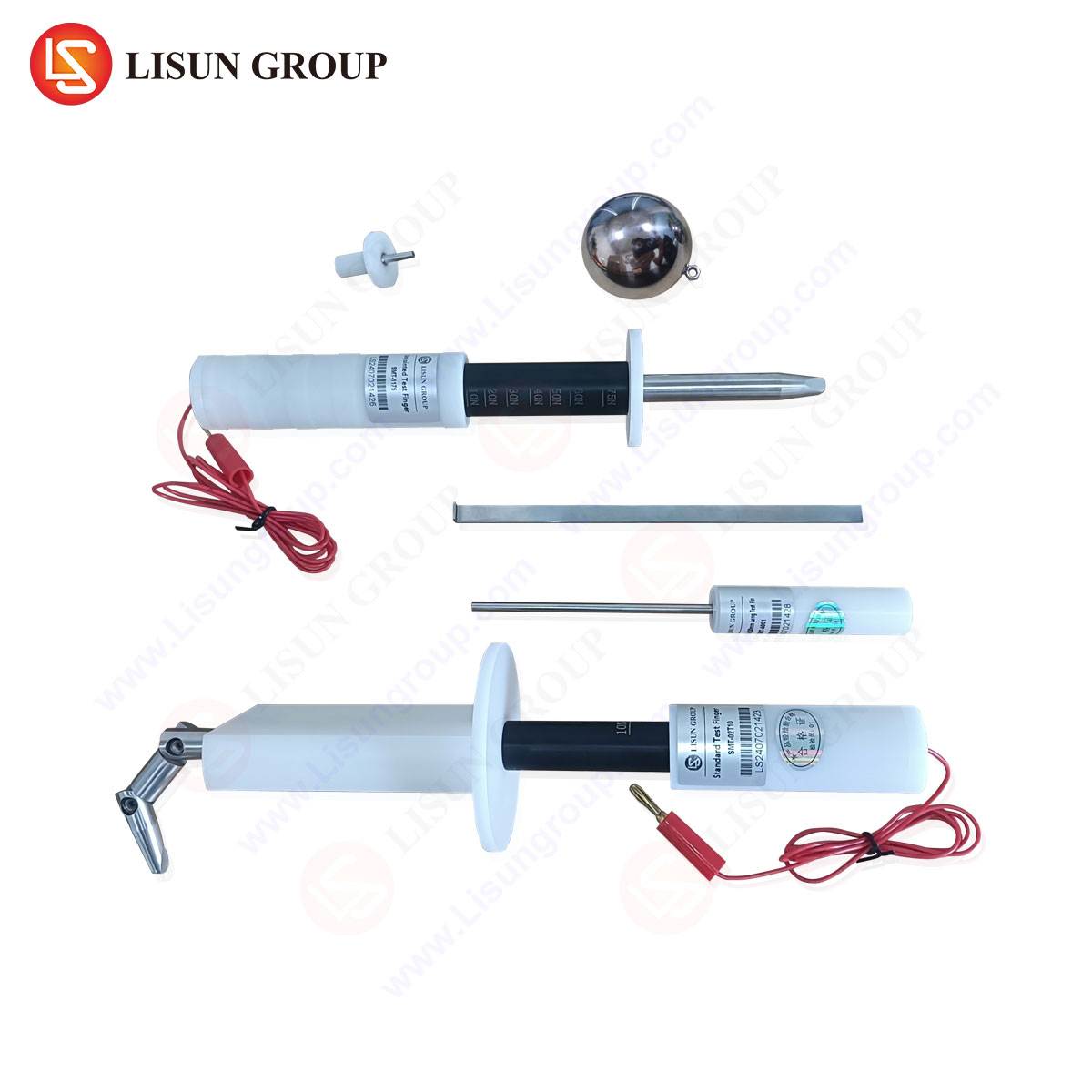
The NF C 61-314 Figure C2 gauge is a composite tool, engineered to perform two distinct but interrelated verification functions. Its design is a direct physical manifestation of the safety principles enshrined within the standard. The gauge is constructed from a rigid, insulating material with precise dimensional tolerances, typically in the order of ±0.05 mm, to ensure repeatable and unambiguous test results. It comprises several key features, each corresponding to a specific clause within NF C 61-314.
The primary function of the gauge is to verify that the shutters or other protective devices within a socket-outlet effectively prevent the insertion of foreign objects. The standard mandates that access to live contacts must be obstructed unless an object with a profile and force application simulating a plug pin is presented. The gauge features a series of standardized probe tips, each with defined diameters, lengths, and geometries. These probes are applied to the socket-outlet with a specified force, typically 1 Newton, and must not activate the shutter mechanism or make contact with live parts. This test simulates attempts to insert commonplace items like keys, hairpins, or small tools, thereby validating the socket’s resistance to such hazardous probing.
A secondary, yet equally critical, function of the gauge is to assess the dimensional compliance of the socket-outlet’s apertures and the configuration of its earth contact. The gauge incorporates elements that mimic the plug pins, ensuring that only a plug conforming to the standard can be inserted. It verifies that the phase and neutral apertures do not allow misalignment or excessive play, which could lead to arcing, overheating, or insecure connections. Furthermore, a specific part of the gauge is designed to engage with the earth contact, checking for correct depth, spring tension, and alignment to guarantee that the earth connection is established before the live pins make contact, a fundamental sequence for user safety.
The Critical Role of Gauge Verification in Socket-Outlet Safety Protocols
The application of the Figure C2 gauge transcends simple dimensional checks; it is a functional test of the socket-outlet’s integrated safety systems. The shutter mechanism, often a spring-loaded or gravity-based assembly, is the first line of defense against electric shock, particularly for children. The gauge’s probes provide a quantitative and repeatable method for assessing the robustness of this defense. A compliant socket must require a force and a specific pin profile—that of a standard plug—to disengage the shutters. If a probe from the gauge can open them, the design is deemed non-compliant, representing a significant safety failure.
Moreover, the verification of the earth pin engagement is paramount. The “early make, late break” principle requires that the earth pin of a plug makes contact before the phase and neutral pins upon insertion, and breaks contact after them upon withdrawal. This ensures that the appliance casing is always grounded before becoming live. The Figure C2 gauge includes a simulated earth pin that is used to verify this sequencing and the mechanical integrity of the earth contact itself. Insufficient contact pressure, measured by the force required to insert and withdraw the gauge element, can lead to a high-resistance connection, resulting in a potential fire hazard or a loss of the protective earth pathway.
Operational Methodology for NF C 61-314 Figure C2 Gauge Application
A standardized testing procedure is essential to ensure that results are consistent and comparable across different laboratories and production facilities. The application of the Figure C2 gauge follows a rigorous protocol. First, the socket-outlet is mounted in a representative manner, as it would be installed in a wall box. The gauge is then carefully aligned with the socket’s face. The various test probes are applied individually to the live contact apertures with the specified force. Any indication of shutter movement or, critically, electrical contact (verified by a circuit continuity test integrated into some advanced gauge systems) constitutes a failure.
Following the probe tests, the main body of the gauge, which simulates the plug’s pin configuration, is inserted. This test checks for smooth insertion without binding or excessive force, and it verifies the alignment of the pins with the internal contacts. The force required for insertion and withdrawal is often measured to ensure it falls within the limits prescribed by the standard, guaranteeing that the socket is neither too loose nor too tight. The entire process is typically conducted under controlled environmental conditions to prevent factors like temperature and humidity from influencing the mechanical properties of the socket’s components.
LISUN Gauges for Plugs and Sockets: Precision Instrumentation for Standards Compliance
In the domain of compliance testing, the accuracy and reliability of the gauge itself are non-negotiable. LISUN provides a comprehensive suite of gauges, including those meticulously manufactured for NF C 61-314 Figure C2, which are engineered to meet the exacting specifications of international standards bodies. LISUN’s implementation of the Figure C2 gauge is crafted from high-strength, dimensionally stable insulating materials that resist wear, deformation, and environmental degradation, ensuring long-term calibration integrity.
The LISUN gauge set is characterized by its exceptional manufacturing precision. Each probe diameter, pin length, and angular dimension is held to tolerances that are significantly tighter than those required by the standard itself. This practice of “gauge maker’s tolerance” ensures that the testing instrument does not introduce measurement uncertainty that could invalidate a pass/fail decision. Furthermore, LISUN offers gauges with optional integrated electrical detection circuits. These advanced models can provide a direct, objective indication of electrical contact during the probe test, eliminating subjective interpretation and enhancing the repeatability of the test outcome.
Key Specifications of LISUN’s NF C 61-314 Figure C2 Gauge:
- Material: High-grade, hardened insulating composite.
- Dimensional Tolerance: ±0.02 mm (exceeding typical requirements).
- Probe Force Application: Calibrated spring mechanism for consistent 1 N application.
- Compliance: Fully conforms to the geometry and testing methodology outlined in NF C 61-314.
- Optional Features: Integrated LED indicator circuit for live contact detection.
Comparative Analysis of Gauge-Based Testing Versus Alternative Verification Methods
While visual inspection and basic caliper measurements can identify gross non-conformities, they are wholly inadequate for verifying the functional safety requirements addressed by the Figure C2 gauge. Visual inspection cannot assess the force required to open shutters or the quality of the earth contact. Simple dimensional tools provide no insight into the dynamic interaction between a plug and a socket.
The Figure C2 gauge, by its very design, provides an integrated test that simulates real-world conditions. It is a pass/fail tool that directly answers the question: “Does this socket-outlet meet the safety requirements of the standard?” Alternative methods, such as 3D scanning or coordinate measuring machines (CMM), can capture detailed dimensional data but are expensive, time-consuming, and still require interpretation to assess functional compliance. They are valuable for R&D and tooling verification but are impractical for high-volume production line testing. The gauge remains the most efficient, direct, and standardized method for compliance verification.
Industry Implications and the Enforcement of Safety Through Standardized Gauging
The ubiquitous use of gauges like NF C 61-314 Figure C2 is a cornerstone of product safety and international trade. For manufacturers, implementing rigorous in-house testing with certified gauges like those from LISUN is a proactive measure to prevent costly batch rejections, recalls, and reputational damage. It enables continuous quality control throughout the production process, from validating injection molds to performing final assembly audits.
For certification bodies and test laboratories, these gauges are the reference instruments upon which product approvals are granted. Their use ensures a level playing field, where all products are evaluated against the same objective criteria. This harmonization is crucial for the CE marking process and for ensuring that products sold in the European Union conform to the Low Voltage Directive. The Figure C2 gauge, therefore, is not just a tool but a physical embodiment of a regulated safety ecosystem, protecting end-users and fostering trust in the electrical products they use daily.
Frequently Asked Questions (FAQ)
Q1: How frequently should a NF C 61-314 Figure C2 gauge be calibrated to maintain testing integrity?
A1: Calibration intervals depend on usage frequency and the laboratory’s quality management system, typically aligned with ISO/IEC 17025 requirements. For high-volume production testing, an annual calibration is a common practice. However, if the gauge is subjected to any impact or shows signs of wear, an immediate recalibration is necessary to ensure its dimensional and functional accuracy remains within the specified tolerances.
Q2: Can the LISUN Figure C2 gauge be used to test socket-outlets from regions other than France?
A2: The NF C 61-314 standard is specific to French-type plugs and socket-outlets. While the underlying safety principles are universal, the dimensional and geometrical requirements differ between standards (e.g., BS 1363 for the UK, DIN VDE 0620-1 for Germany). The LISUN Figure C2 gauge is designed exclusively for NF C 61-314 compliance. LISUN provides a distinct portfolio of gauges tailored to other national and international standards.
Q3: What is the consequence of a socket-outlet failing the probe test with the Figure C2 gauge?
A3: A failure during the probe test indicates that the shutter mechanism is insufficiently robust to prevent access to live parts by a foreign object. This constitutes a critical safety failure, rendering the socket-outlet non-compliant and unsafe for the market. The design of the shutter assembly, including spring tension, pivot points, and tolerances between components, must be re-engineered and validated before production can resume.
Q4: Does the LISUN gauge account for the wear and tear that a socket might experience over its lifetime?
A4: The standard gauge test is performed on new socket-outlets. However, standards like NF C 61-314 often include durability tests, such as a specified number of mechanical operation cycles (insertions and withdrawals of a test plug), which are performed separately. After these endurance tests, the socket is re-evaluated with the gauge to ensure that safety features, like shutter operation and contact pressure, remain effective after simulated long-term use. The robustness of the LISUN gauge material ensures it can be used reliably for both initial and post-endurance verification.