


Optimizing Temperature Testing for Enhanced Product Reliability and Compliance
The validation of product performance and longevity under extreme thermal conditions constitutes a fundamental pillar of modern engineering and quality assurance. As technological components become increasingly integrated and miniaturized, their susceptibility to temperature-induced failure modes—ranging from material degradation and solder joint fatigue to parametric drift and catastrophic malfunction—escalates correspondingly. Consequently, precise, repeatable, and standards-compliant environmental testing is not merely a procedural step but a critical risk mitigation strategy. This article examines methodologies for optimizing temperature testing protocols, with a specific focus on the application of advanced test chambers, exemplified by the LISUN HLST-500D Thermal Shock Test Chamber, to accelerate product development cycles and ensure market-ready reliability.
The Imperative of Accelerated Thermal Stress Testing
Traditional steady-state temperature cycling, while valuable, often requires extended durations to precipitate latent defects. Accelerated thermal shock testing, by contrast, subjects test specimens to rapid transitions between extreme high and low temperatures. This methodology induces high-magnitude thermal stresses within a condensed timeframe, effectively simulating years of operational thermal cycling or exposure to severe environmental shocks within hours or days. The primary objective is to identify weaknesses in material compatibility, assembly integrity, and component resilience that might otherwise remain undetected until field failure. The physics underpinning this process involves the differential coefficients of thermal expansion (CTE) of bonded materials. Rapid temperature change causes these materials to expand and contract at dissimilar rates, generating shear and tensile stresses at interfaces such as solder joints, bonded layers, and encapsulated modules.
Operational Principles of the Two-Zone Thermal Shock Chamber
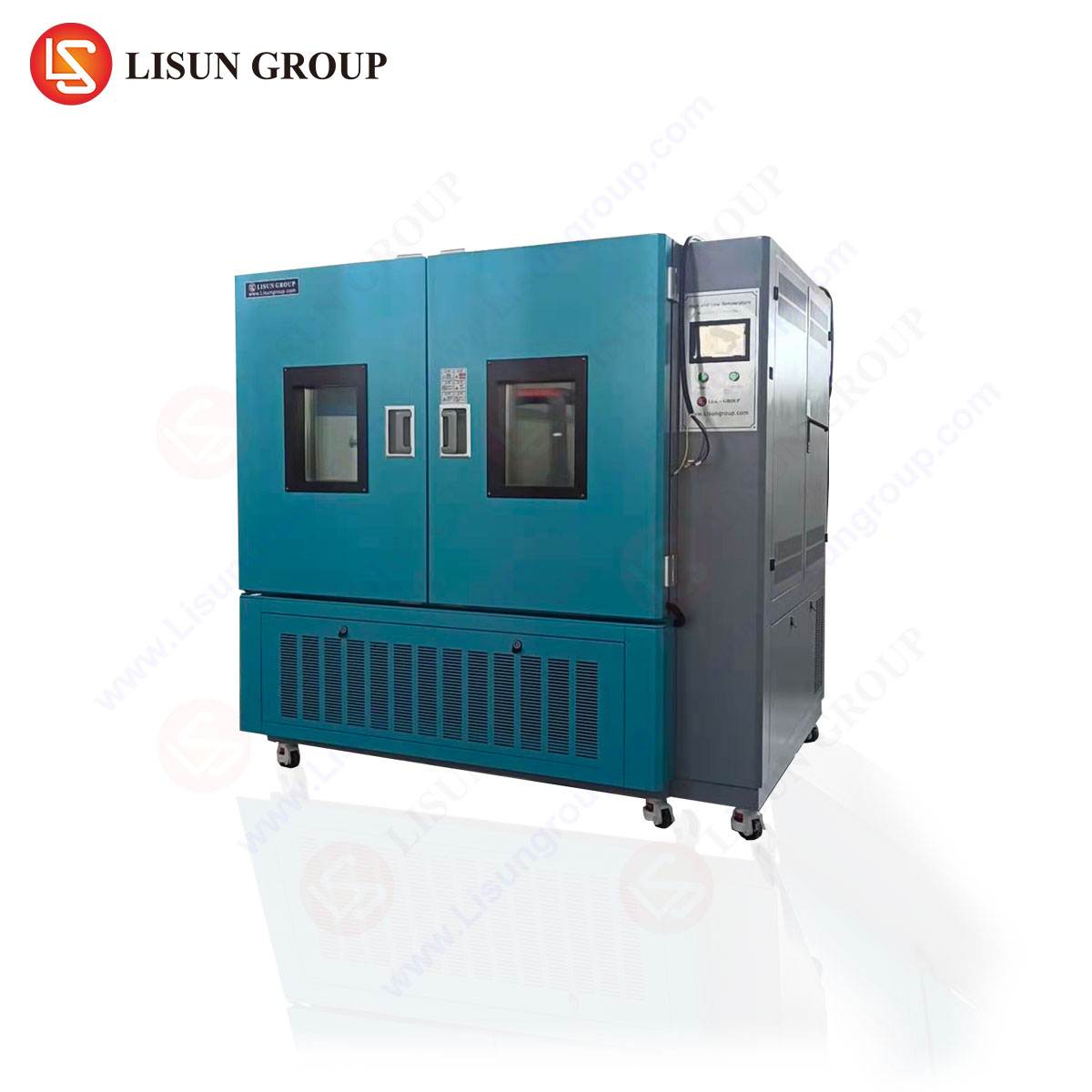
The LISUN HLST-500D Thermal Shock Test Chamber employs a widely recognized and efficient two-zone (basket transfer) architecture to execute these rigorous tests. The system comprises two independently controlled climatic zones: a high-temperature zone and a low-temperature zone. A mechanically driven basket, which holds the test specimens, shuttles rapidly between these two chambers. This design philosophy prioritizes extreme transition speed and temperature stability within each zone, as the chambers themselves are not required to dynamically ramp. Instead, they maintain strict setpoints, allowing the basket and its payload to experience a near-instantaneous change in ambient environment upon transfer.
The testing cycle is defined by several key parameters: the high and low temperature setpoints, the dwell time at each extreme, and the transfer time. The dwell time must be sufficient for the test specimen to achieve thermal equilibrium throughout its mass, a factor dependent on its thermal mass and conductivity. The transfer time, typically under 10 seconds for a chamber like the HLST-500D, is crucial for achieving the desired shock effect. Prolonged transfer diminishes the thermal gradient experienced by the unit under test (UUT). The chamber’s control system automates this sequence, enabling precise repetition over hundreds or thousands of cycles to meet stringent test standards such as IEC 60068-2-14, MIL-STD-202, and JESD22-A104.
Technical Specifications and System Architecture of the HLST-500D
The efficacy of a thermal shock test is directly contingent upon the performance specifications and construction of the chamber. The LISUN HLST-500D is engineered to deliver precise and reliable testing conditions, as outlined in the following key specifications:
| Parameter | Specification |
|---|---|
| Test Volume | 500 Liters |
| High Temperature Range | +60°C to +200°C |
| Low Temperature Range | -10°C to -65°C (or -80°C with optional LN2 cooling) |
| Temperature Recovery Time | ≤ 5 minutes (from ambient to extreme setpoints) |
| Temperature Fluctuation | ≤ ±0.5°C |
| Temperature Uniformity | ≤ ±2.0°C |
| Basket Transfer Time | ≤ 10 seconds |
| Dwell Time Range | 0 to 999 hours, 59 minutes |
| Control System | Programmable touch-screen controller, RS-485 interface |
The chamber’s architecture features high-efficiency heating elements and a dual-stage mechanical refrigeration system for cooling, ensuring rapid temperature recovery after basket transfer. The inner chamber is constructed from SUS#304 stainless steel, providing corrosion resistance and thermal durability. The basket mechanism is designed for smooth, high-speed operation with minimal vibration transmission to the UUT. Advanced insulation between the two zones minimizes thermal cross-talk, preserving the integrity of each zone’s environment. The programmable controller allows for complex multi-segment test profiles, data logging, and real-time monitoring of both zone temperatures and system status.
Industry-Specific Applications and Failure Mode Analysis
The application of thermal shock testing spans industries where electronic and electromechanical components face demanding environments. The HLST-500D facilitates targeted validation for a diverse range of products.
Automotive Electronics and Industrial Control Systems: Modern vehicles and industrial machinery embed sophisticated control units, sensors, and power electronics. A engine control unit (ECU) may be subjected to under-hood temperatures exceeding 125°C while in operation, yet experience ambient winter temperatures when idle. Thermal shock testing validates the integrity of ball grid array (BGA) solder joints, the stability of conformal coatings, and the performance of electrolytic capacitors under such rapid transitions. Similarly, programmable logic controllers (PLCs) in industrial settings must withstand thermal stresses from internal heat generation and external plant conditions.
Telecommunications Equipment and Aerospace Components: Base station electronics and avionics are deployed in environments with severe diurnal temperature swings. Testing with the HLST-500D can uncover delamination in multilayer printed circuit boards (PCBs), creep in connector housings, or fracture in crystal oscillators. The rapid cycling accelerates the fatigue life assessment of these critical components.
Medical Devices and Consumer Electronics: Implantable devices, diagnostic equipment, and handheld electronics demand exceptional reliability. Thermal shock testing simulates the stress of sterilization cycles for medical tools, or the repeated transition from a warm indoor environment to a cold vehicle for a smartphone. It tests the seals of waterproof enclosures, the adhesion of display laminates, and the functionality of miniature batteries.
Electrical Components, Lighting, and Cable Systems: Switches, sockets, LED drivers, and wiring harnesses are tested for contact resistance stability, plastic housing brittleness, and insulation integrity. A failure in a connector due to pin retraction under cold shock, for instance, can be identified and rectified during the design phase through this testing regimen.
Strategic Advantages in Product Development and Qualification
Integrating a chamber like the HLST-500D into a product development lifecycle confers several strategic advantages beyond basic compliance.
Accelerated Time-to-Market: By rapidly identifying design and assembly flaws, engineers can implement corrective actions earlier in the design process, avoiding costly late-stage redesigns or post-release field retrofits.
Enhanced Predictive Failure Analysis: The test provides empirical data on a product’s weakest points under thermal stress. This data informs finite element analysis (FEA) models, improving their accuracy for future virtual prototyping and reducing physical test iterations.
Supply Chain Validation: The chamber is instrumental in qualifying components from second-source suppliers or new manufacturing processes. Verifying that a new batch of integrated circuits or a changed solder paste formulation can withstand thermal shock ensures consistent product quality.
Correlation to Field Reliability: When calibrated against known field failure data, accelerated thermal shock test profiles can be refined to become highly predictive of actual product lifespan, transforming testing from a pass/fail gate into a quantitative reliability engineering tool.
Optimizing Test Protocols for Specific Product Categories
A one-size-fits-all approach to thermal shock testing is ineffective. Optimization requires tailoring the test profile to the product’s materials, construction, and end-use environment.
For high thermal mass products like large power supplies or industrial motor drives, dwell times must be extended to ensure core components reach the setpoint temperature. Thermocouples should be attached to both surface and internal locations to verify equilibrium.
For miniaturized consumer electronics with dense component packaging, the focus shifts to the CTE mismatch between silicon dies, underfill material, and the substrate. Faster transfer times and a wider temperature delta (e.g., -55°C to +125°C) may be employed to maximize stress on micro-scale interconnects.
For sealed or potted assemblies, such as sensors or outdoor telecommunications gear, testing must verify that the sealing compound does not crack or detach from the housing or leads, compromising ingress protection (IP) ratings. Post-test inspection often includes helium leak testing or visual examination under magnification.
Functional monitoring during testing—where the UUT is powered and its electrical parameters are measured in situ during dwell periods—is a critical optimization. It allows for the detection of intermittent failures or parametric shifts that occur only at temperature extremes, which a simple post-test functional check would miss.
Compliance and Standards Integration
A robust testing program is anchored in relevant international standards. The HLST-500D is designed to facilitate testing per major industry specifications:
- IEC 60068-2-14: Environmental testing – Part 2-14: Tests – Test N: Change of temperature.
- MIL-STD-202G: Test Method Standard for Electronic and Electrical Component Parts.
- MIL-STD-883K: Test Method Standard for Microcircuits.
- JESD22-A104: Temperature Cycling.
- GB/T 2423.22: Chinese standard for environmental testing – Change of temperature.
The programmability of the chamber controller allows users to directly implement the dwell times, temperature extremes, and cycle counts stipulated by these standards, ensuring that test reports are audit-ready and recognized by certification bodies globally.
Frequently Asked Questions (FAQ)
Q1: What is the critical difference between temperature cycling and thermal shock testing, and when should I specify the latter?
Temperature cycling typically involves slower ramp rates (e.g., 1°C to 10°C per minute) between extremes, focusing on fatigue over many cycles. Thermal shock utilizes near-instantaneous transfers (≤10 seconds) to create high-rate thermal gradients, emphasizing mechanical stress from CTE mismatch. Specify thermal shock for components that will experience rapid environmental changes (e.g., powering on in a cold environment, outdoor-to-indoor transitions) or to quickly screen for gross assembly and workmanship defects.
Q2: How do I determine the appropriate high and low temperature setpoints and dwell times for my product?
Setpoints should be derived from the product’s operational and storage specifications, with an added margin for safety. Common ranges are -40°C to +125°C for automotive, -55°C to +85°C for military/aerospace, and 0°C to +70°C for commercial electronics. Dwell time must be sufficient for thermal stabilization. This is best determined by placing thermocouples on the product’s critical components during a preliminary cycle and extending the dwell until their temperatures plateau within a few degrees of the chamber air temperature.
Q3: Can the HLST-500D accommodate powered testing (in-situ monitoring)?
Yes, but it requires planning. The chamber basket must be fitted with appropriate electrical feed-through ports. These ports allow wiring to connect the unit under test inside the chamber to external power supplies and measurement equipment outside. It is essential to use wiring that remains flexible at low temperatures to prevent breakage and to manage the heat load introduced by powering the UUT, as it may slightly affect chamber recovery times.
Q4: What maintenance is required to ensure the long-term accuracy and reliability of the thermal shock chamber?
Regular preventive maintenance is crucial. Key tasks include: checking and cleaning the door seals for integrity; inspecting the basket drive mechanism for smooth operation; cleaning condenser coils on the refrigeration system to maintain efficiency; verifying calibration of temperature sensors annually against a NIST-traceable standard; and ensuring the lubricant in the compressor is maintained at the proper level. A well-maintained chamber ensures consistent test conditions and reproducible results over its service life.