


A Comprehensive Framework for Photovoltaic Inverter Safety Testing: Methodologies, Standards, and Critical Evaluation Tools
Introduction to Safety Imperatives in Photovoltaic Power Conversion
The proliferation of grid-connected and off-grid photovoltaic (PV) systems has positioned the inverter as the critical nexus between DC power generation and AC power utilization. As the core intelligence of a PV array, the inverter manages maximum power point tracking, grid synchronization, and system diagnostics. However, its fundamental role in energy conversion also renders it a focal point for potential electrical, mechanical, and fire hazards. Comprehensive safety testing is therefore not merely a regulatory hurdle but an essential engineering discipline to ensure end-user protection, equipment longevity, and grid stability. This article delineates the multifaceted safety testing regimen for PV inverters, emphasizing the pivotal role of standardized mechanical access probes in verifying protection against live parts. The discourse integrates references to international standards, practical testing scenarios across multiple industries, and an examination of specialized instrumentation, including the LISUN series of test fingers, probes, and pins.
Evaluating Protection Against Access to Hazardous Live Parts: The Role of Standardized Probes
A paramount safety objective for any enclosed electrical equipment is to prevent user contact with hazardous voltages. For PV inverters, which house both high-voltage DC inputs (often up to 1500V DC) and AC output circuits, this protection is assessed through stringent mechanical tests defined in standards such as IEC 62109, IEC 62116, and the broader IEC 60529 (Ingress Protection – IP Code) and IEC 61032. These tests verify that openings in enclosures—whether for cooling, control interfaces, or cable entry—do not permit access by fingers, tools, or wires to live parts under normal or single-fault conditions.
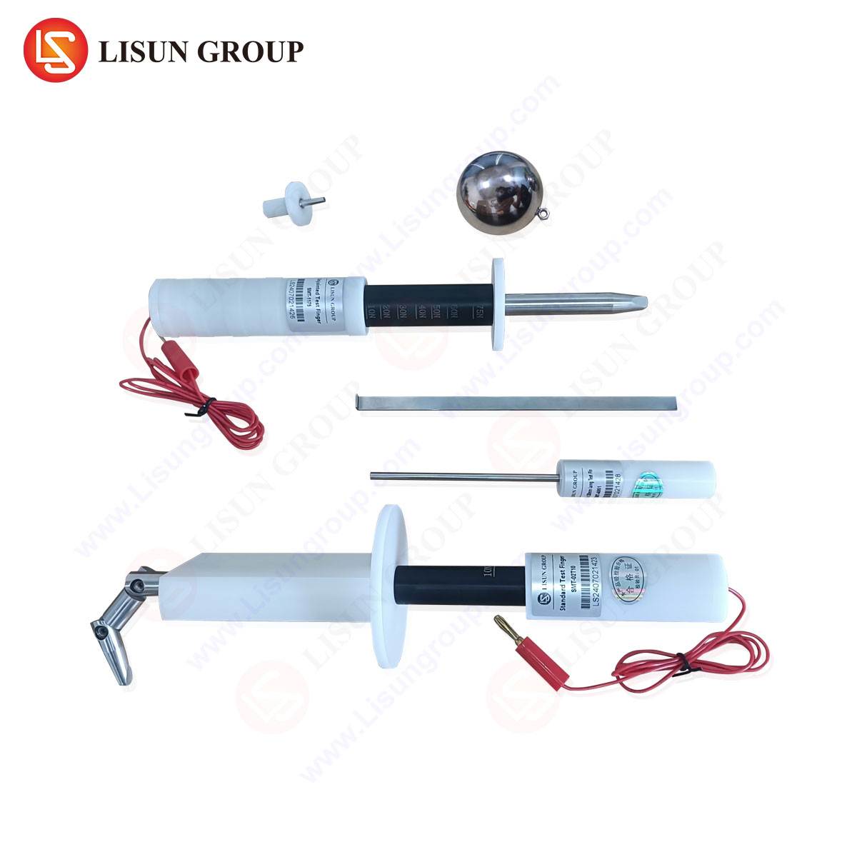
The testing employs geometrically defined probes that simulate human appendages and common objects. The LISUN Test Finger (model LS-JX01, compliant with IEC 61032 Figure 2, IEC 60529, and UL 507) is a seminal tool in this suite. Constructed from rigid metal with articulated joints, it simulates the dimensions of a human finger (80mm long, 12mm diameter joint, 20mm diameter tip). Its application is systematic: with a test force of 10N ± 1N, the probe is inserted into every opening of the inverter enclosure. The pass criterion is defined by the inability of the probe to contact any live part or uninsulated moving part. A secondary verification, often using a “test lamp” circuit with a voltage not less than 40V and not more than 50V, is connected between the probe and live parts. Illumination of the lamp indicates unacceptable contact. This test is directly relevant not only to PV inverters but also to Household Appliances, Consumer Electronics, and Electrical Components like switches and sockets, where user-accessible openings are common.
For smaller apertures, the LISUN Test Probe (model LS-JX02, compliant with IEC 61032 Figure 1) is utilized. This straight, unjointed steel probe of 100mm length and 4mm diameter simulates a stiff wire or tool. Applied with a force of 1N ± 0.1N, it must not penetrate to touch hazardous parts. This is critical for inverter cooling vents, terminal block shrouds, and communication ports. In parallel industries, such as Telecommunications Equipment and Industrial Control Systems, similar probes assess the safety of data ports and ventilation slots.
The LISUN Test Pin (model LS-JX03, compliant with IEC 61032 Figure 3) addresses even finer vulnerabilities. This 15mm long probe, with a 3mm diameter handle tapering to a 0.5mm diameter tip, is applied with a force of 0.5N ± 0.05N. Its purpose is to verify that openings deemed to provide “protection against access with a tool” are indeed secure. In PV inverters, this may apply to small adjustment holes or certain types of service interfaces. The principle extends to Toy and Children’s Products Industry, where probes simulate small parts that could be inserted by a child, and to Aerospace and Aviation Components, where vibration-resistant design must not create unforeseen access points.
Dielectric Strength and Insulation Coordination Testing
Beyond physical access, the integrity of electrical insulation is validated through dielectric strength (hipot) testing. This involves applying a high AC or DC voltage (e.g., 2U + 1000V, as per IEC 62109) between live parts and accessible conductive parts for one minute. The test verifies that insulation materials, creepage distances, and clearances are sufficient to withstand transient overvoltages, such as those from lightning strikes or grid switching events. A critical precursor to this high-voltage test is often a verification that the test probes mentioned previously cannot bypass this insulation, making the mechanical and electrical tests deeply interdependent.
Thermal Management and Fire Hazard Assessment
PV inverters operate with high power densities, making thermal performance a direct safety concern. Testing involves operating the unit at rated power and worst-case ambient temperatures (often 40°C or 50°C) while monitoring temperatures of critical components—semiconductors, magnetics, PCB traces, and enclosure surfaces—using thermocouples. Limits are defined by the material ratings (e.g., UL 94 for flammability of plastics) and safety standards to prevent overheating that could lead to insulation degradation, component failure, or ignition of surrounding materials. Automotive Electronics and Lighting Fixtures undergo analogous thermal stress tests, given their often confined, high-temperature operating environments.
Abnormal Operation and Fault Condition Testing
Safety must be maintained under foreseeable fault conditions. For inverters, this includes tests for:
- Output Short-Circuit: Verifying the inverter safely shuts down without creating a fire hazard.
- Islanding Protection: As mandated by IEC 62116, ensuring the inverter detects a grid outage and disconnects within a specified time to prevent “islanding,” which endangers utility workers.
- Input Overvoltage/Undervoltage: Testing response to abnormal DC string voltages.
- Cooling System Failure: Assessing behavior under fan failure or blocked ventilation, closely tied to thermal testing.
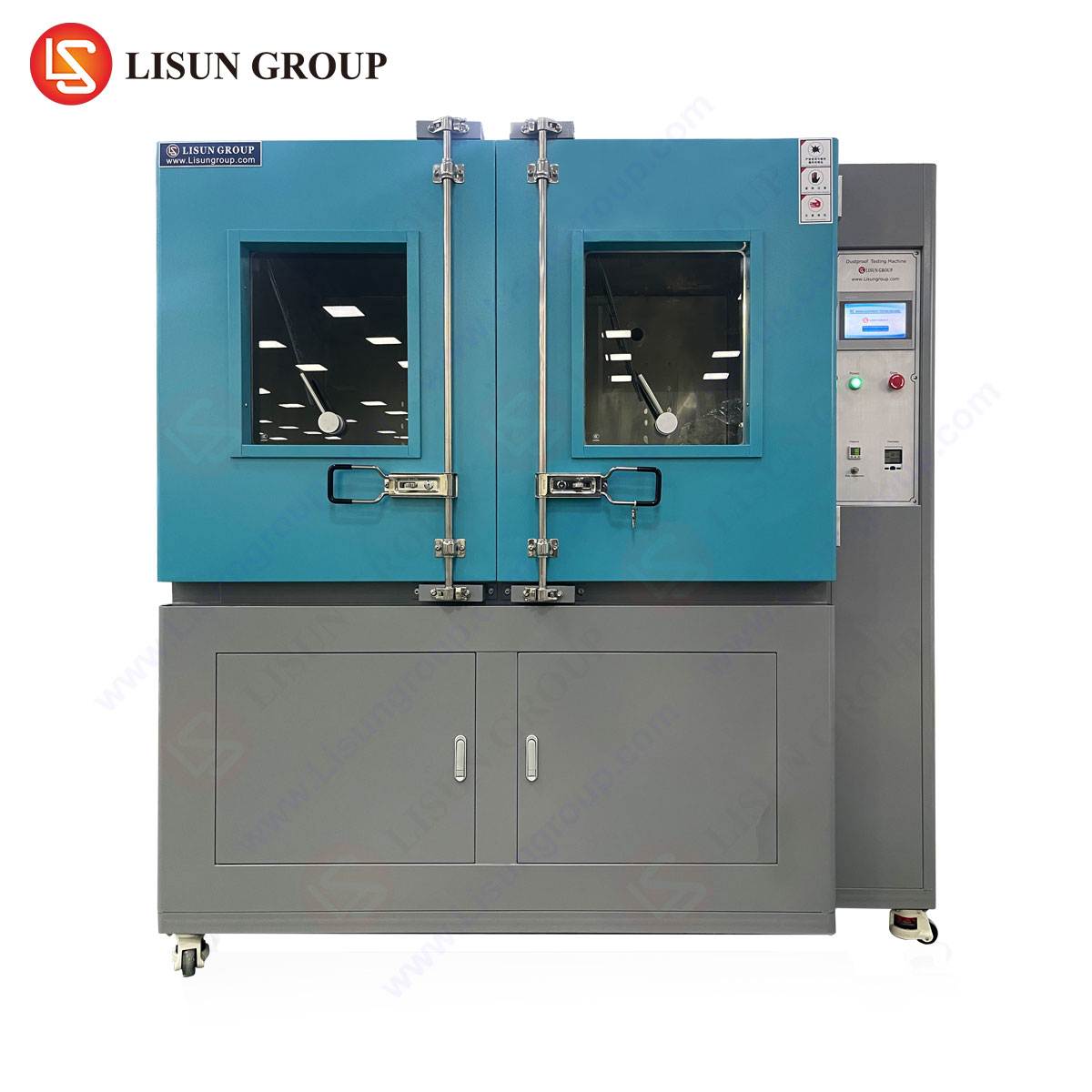
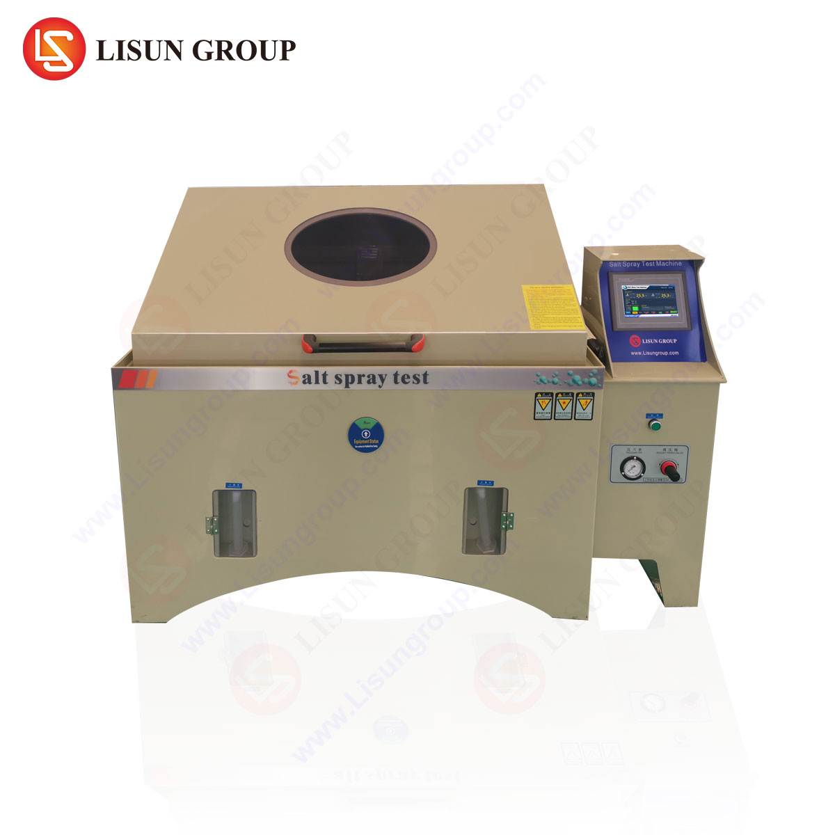
Ingress Protection (IP) Rating Validation for Environmental Durability
The IP rating (e.g., IP65) denotes protection against solid objects and water. Testing involves dust chambers and water jets/sprays per IEC 60529. For outdoor inverters, a minimum of IP65 is typical, ensuring dust-tightness and protection against water jets. This is equally vital for Industrial Control Systems in harsh environments and Outdoor Lighting Fixtures.
The Instrumentation Imperative: Precision, Compliance, and Repeatability
The validity of safety testing hinges on the precision and traceable compliance of the tools used. Generic or improvised probes introduce unacceptable variables. Specialized equipment, such as the LISUN test series, provides calibrated, anodized steel construction with exact dimensional tolerances as per international standards. The competitive advantage of such dedicated instrumentation lies in:
- Standard Compliance: Direct alignment with the figures and specifications in IEC 61032, IEC 60529, UL, and GB standards, ensuring audit readiness.
- Metrological Traceability: Calibration certificates linking measurements to national standards.
- Durability: Hardened materials resist deformation, ensuring test consistency over thousands of applications across product batches.
- Ergonomics: Designed handles and force gauges facilitate the precise application of mandated test forces (0.5N, 1N, 10N).
Cross-Industry Application of Mechanical Access Probe Testing
The principles governing PV inverter safety testing are ubiquitous across the electrotechnical landscape. The following table illustrates the application:
| Industry | Application Example | Relevant Probe | Standard | Test Objective |
|---|---|---|---|---|
| Household Appliances | Blender housing slots, power socket openings. | Test Finger, Test Pin | IEC 60335 | Prevent finger/wire contact with mains parts. |
| Medical Devices | Patient-connected monitoring equipment enclosures. | Test Finger, Test Probe | IEC 60601 | Ensure no hazardous access in normal or single-fault condition. |
| Automotive Electronics | EV charging port, onboard converter housings. | Test Probe, Test Pin | ISO 20653 | Verify protection against tools and environmental ingress. |
| Office Equipment | Power supply vents in printers, copiers. | Test Finger | IEC 60950-1 / 62368-1 | Assess accessibility of hazardous energy sources. |
| Cable & Wiring Systems | Connector housings, junction boxes. | Test Pin, Test Probe | IEC 61984 | Check that live pins are recessed or shielded. |
Conclusion: A Synthesis of Mechanical and Electrical Verification
The safety certification of a photovoltaic inverter is a holistic process synthesizing mechanical, electrical, thermal, and environmental validations. Mechanical access probe testing forms the foundational, physical verification layer, ensuring that the primary barrier—the enclosure—is conceptually sound before high-potential and functional safety tests are applied. The use of standardized, calibrated instrumentation like the LISUN test finger, probe, and pin is not a procedural formality but a critical enabler of repeatable, internationally recognized safety outcomes. As inverter topologies evolve and system voltages increase, the rigor of these fundamental tests will remain a constant, underpinning the safe expansion of renewable energy infrastructure and paralleling the safety engineering disciplines across the entire spectrum of electrical and electronic equipment manufacturing.
FAQ Section
Q1: Why is the specific geometry and applied force of the test finger so critical?
The dimensions (modeled on a small child’s finger) and the 10N force are statistically derived to represent a credible worst-case scenario for unintentional contact by a user. Deviating from the standard geometry or force could yield false positives or negatives, compromising the safety assessment. The design ensures global consistency in evaluating “finger-safe” designs.
Q2: Can a product pass the test finger test but fail the test probe test?
Absolutely. These are complementary tests for different levels of protection. A grille might successfully block a finger (12mm joints) but may allow a 4mm rigid wire (test probe) to penetrate if the spacing is incorrect. Standards often require multiple probes to be applied sequentially to verify “ordinary person” and “instructed person” protection levels.
Q3: How often should test probes like the LISUN series be calibrated or replaced?
Calibration intervals are typically annual, depending on lab accreditation requirements and usage frequency. The probes should be inspected before each use for signs of physical damage (bends, tip blunting). A damaged probe must be taken out of service immediately, as its non-standard geometry invalidates any test results.
Q4: Are these tests only for final product certification, or are they used in design?
They are integral to both. During the design and prototyping phase (Design Verification), engineers use these probes to identify and rectify access hazards early. During formal Type Testing for certification, they are used by accredited labs for compliance validation. Incoming Quality Control (IQC) may also use them to audit production units.
Q5: With the transition from IEC 60950/60065 to IEC 62368-1, have the probe specifications changed?
The fundamental probe specifications defined in IEC 61032 remain the primary reference. IEC 62368-1, as a hazard-based standard, references these same probes for evaluating safeguards against access to hazardous energy sources. The continuity in tooling ensures that existing, compliant instrumentation remains valid under the newer standard.