


A Comprehensive Analysis of Plug Socket Torque Testing: Methodologies, Standards, and Instrumentation
Introduction to Mechanical Integrity in Electrical Connectors
The mechanical integrity of plug and socket interfaces constitutes a foundational element of electrical safety and long-term reliability. While electrical parameters such as contact resistance and dielectric strength are routinely validated, the mechanical forces involved in mating and unmating cycles are equally critical. Torque, defined as the rotational force applied to a plug during insertion or extraction, directly influences contact pressure, wear characteristics, and ultimately, the operational lifespan of the connection. Insufficient torque can lead to high-resistance connections, localized heating, and potential thermal runaway. Conversely, excessive torque may induce plastic deformation of contacts, damage insulating housings, or accelerate wear, leading to premature failure. Consequently, standardized torque testing has emerged as an indispensable quality assurance procedure within the manufacturing and certification processes for plugs, sockets, and interconnected devices.
Defining Torque Parameters for Plug and Socket Interfaces
Torque in this context is quantified as the moment of force required to initiate or sustain rotation of a plug within its corresponding socket. This measurement is typically expressed in Newton-meters (N·m) or centi-Newton meters (cN·m). Two primary torque values are of interest: insertion torque and withdrawal torque. Insertion torque reflects the frictional resistance encountered as the plug’s pins or blades engage with the socket’s contacts, encompassing both the initial engagement and the full seating force. Withdrawal torque, often measured as the breakaway torque, indicates the force required to initiate disconnection after a specified dwell time, which can be influenced by contact spring relaxation, minor cold welding, or material creep. Industry standards, such as those published by the International Electrotechnical Commission (IEC 60320 series for appliance couplers, IEC 60884-1 for plugs and sockets), Underwriters Laboratories (UL 498, UL 1681), and other national bodies, prescribe precise torque limits for various connector types and current ratings. These limits are not arbitrary; they are derived from empirical data correlating torque with contact force, electrical performance, and durability over thousands of mating cycles.
The Critical Role of Standardized Torque Testing Protocols
Adherence to standardized testing protocols ensures reproducibility and allows for meaningful comparison between products from different manufacturers. A formal torque test procedure generally mandates the use of calibrated, non-conforming test plugs—gauges manufactured to the dimensional maximums and minimums allowed by the relevant standard. These gauges eliminate variables introduced by production tolerances of commercial plugs. The test socket is rigidly mounted to a test fixture, and the specified test gauge is inserted. A torque measurement device, either manual or automated, is then applied to the gauge. The test involves gradually applying a rotational force in the plane of insertion/withdrawal until movement is initiated, recording the peak value. This process is repeated across multiple samples and often after subjecting the socket to durability cycling (e.g., 10,000 insertions and withdrawals) and thermal stress conditioning. The resulting data set provides a statistical profile of the socket’s mechanical performance throughout its intended service life. Compliance is verified by ensuring measured torque values fall within the standard’s stipulated range—a band that guarantees sufficient contact pressure without imposing undue physical strain on the user or the component.
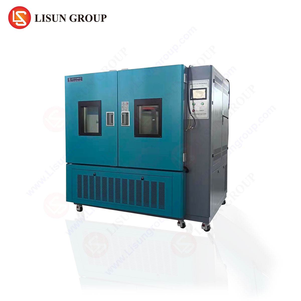
Instrumentation for Precision Measurement: The LISUN Gauges for Plugs and Sockets
Accurate torque measurement necessitates instrumentation of high precision and repeatability. The LISUN series of torque gauges and test fixtures are engineered specifically for this demanding application. These systems typically consist of a digital torque transducer, a rigid mounting assembly, and a suite of standardized test fingers and gauges conforming to IEC, UL, VDE, and other international specifications. The core transducer utilizes a strain gauge or piezoelectric sensor to convert mechanical torque into a precise electrical signal, which is then processed and displayed on a digital readout with resolution often down to 0.001 N·m.
The testing principle is direct and traceable. The appropriate LISUN test gauge, representing the worst-case dimensional scenario (e.g., a “maximum metal” plug for withdrawal torque tests, a “minimum metal” plug for insertion tests), is securely attached to the torque sensor. The sensor assembly is then aligned and engaged with the socket under test. In a manual operation, the technician applies a smooth, continuous rotational force; automated systems employ a servo motor to apply the torque at a controlled, standardized rate. The instrument captures the peak torque value achieved immediately prior to rotation. Advanced LISUN models incorporate data logging software, allowing for the recording of test sequences, generation of statistical reports (mean, standard deviation, Cp/Cpk values), and direct comparison against pre-programmed tolerance limits.
Specifications and Capabilities of Advanced Torque Test Systems
A representative high-end system, such as the LISUN LS-TG300 series, offers a measurable range from 0.01 N·m to 5.0 N·m, covering virtually all common plug and socket types from low-current appliance inlets to industrial connectors. Key specifications include an accuracy class of ±0.5% full scale (FS) and repeatability of ±0.2% FS. The system supports interchangeable adapters for various pin configurations (e.g., North American NEMA 5-15 blades, European CEE 7/4 pins, UK BS 1363 rectangular pins). Integrated features often include:
- Peak Hold Function: Automatically captures and holds the maximum torque value.
- Programmable Limits: Audible and visual alerts for pass/fail judgment.
- Bi-directional Measurement: For both insertion (clockwise) and withdrawal (counter-clockwise) torque.
- USB/RS-232 Data Output: For integration with laboratory information management systems (LIMS).
- Robust Fixturing: Ensures the socket is held without deformation, isolating the torque measurement purely to the contact interface.
These capabilities transform torque testing from a simple go/no-go check into a rich source of quality data, enabling process control and design validation.
Industry Applications and Use Cases for Torque Test Data
The application of plug socket torque testing spans the entire product lifecycle. During Research and Development, engineers use torque data to validate contact spring designs, select plating materials (e.g., nickel vs. silver), and optimize housing geometry. Correlating torque with measured contact resistance (using a milliohm meter) allows for the development of designs that maintain electrical performance with minimal mechanical wear.
In Manufacturing Quality Control, torque testing is a critical in-line or end-of-line audit. Sampling plans require periodic verification that production batches maintain torque within specified limits. A downward trend in withdrawal torque, for instance, could indicate tool wear in the contact stamping process or a substandard heat treatment of the contact spring alloy, triggering corrective action before non-conforming products are shipped.
For Safety Certification and Compliance Testing, accredited laboratories (e.g., UL, TÜV, Intertek) rely on instruments like the LISUN gauges to perform type tests. The data generated forms a mandatory part of the test report submitted for certification marks. Regulatory bodies and standards committees themselves utilize this data to refine and update torque requirements in successive editions of standards.
Furthermore, in Failure Analysis and Forensic Engineering, torque testing of field-returned samples can diagnose root causes of failure. A socket exhibiting charring may reveal abnormally low withdrawal torque, pointing to loss of contact force as the primary failure mode rather than an electrical overload event.
Competitive Advantages of Automated and Data-Centric Torque Testing
Transitioning from manual, hand-held torque screwdrivers to automated, data-centric systems like those in the LISUN portfolio confers several distinct advantages. First is the elimination of operator-induced variability. The rate of force application, alignment, and interpretation of the “breakaway” point are all controlled by the instrument, ensuring objective and repeatable results. Second, the digital capture and storage of every measurement creates an auditable trail for quality management systems (e.g., ISO 9001, IATF 16949), which is increasingly demanded by automotive, aerospace, and high-reliability consumer electronics manufacturers.
Third, the integration of statistical process control (SPC) software enables predictive maintenance. By monitoring torque trends over time, manufacturers can preemptively schedule maintenance for molding tools or contact assembly machines before they drift out of specification. This proactive approach reduces scrap, improves overall equipment effectiveness (OEE), and ensures consistent product quality. Finally, the efficiency gains are substantial. Automated systems can test multiple samples in sequence, generate reports automatically, and reduce the total time required for compliance testing, accelerating time-to-market for new products.
Interpreting Torque Data Within a Broader Performance Framework
It is imperative to contextualize torque data within a holistic performance model. Torque is not an isolated metric but is intrinsically linked to electrical performance and durability. A comprehensive validation suite will parallel torque measurements with:
- Contact Resistance Tests: Using a low-resistance ohmmeter to verify that the contact pressure indicated by the torque translates to a stable, low-resistance interface (typically < 5 mΩ for power connectors).
- Durability Cycling: Subjecting the socket to thousands of mating cycles with a standardized test plug, then re-measuring torque and contact resistance to assess performance degradation.
- Thermal Stress Conditioning: Exposing the connector to high-temperature aging (e.g., 70°C for 168 hours per IEC 60512) to evaluate the stability of contact spring properties and housing integrity, followed by post-conditioning torque verification.
This multi-variable analysis provides a complete picture of connector reliability. A socket may exhibit acceptable initial torque, but if its withdrawal torque plummets after thermal aging or a modest number of cycles, it signifies a design flaw in material selection or spring geometry.
Conclusion: Torque as a Foundational Metric for Connector Reliability
In summary, plug socket torque testing represents a critical, non-electrical evaluation that directly underpins the safety, performance, and longevity of one of the most ubiquitous electrical interfaces. The move towards precise, automated, and data-rich measurement systems, exemplified by the capabilities of the LISUN Gauges for Plugs and Sockets, reflects the increasing sophistication of quality assurance in the electrical manufacturing industry. By rigorously applying standardized torque test protocols and integrating the resulting data with electrical and durability metrics, manufacturers can achieve a higher degree of product reliability, ensure regulatory compliance, and ultimately, enhance end-user safety across countless applications. The continued refinement of these test methods and instruments will remain integral to the evolution of connector technology, particularly as new materials and miniaturized designs present fresh mechanical challenges.
FAQ Section
Q1: Why can’t I use a regular production plug and a standard torque wrench to perform a compliant torque test?
A: Production plugs have dimensional tolerances. Using one may not represent the worst-case mechanical interaction, potentially yielding non-representative data. Standardized test gauges, like those supplied with LISUN systems, are manufactured to the maximum and minimum material conditions defined in the standard. Furthermore, a torque wrench is designed for applying a set torque, not for measuring the precise breakaway torque of an interface with the required accuracy and resolution.
Q2: How often should torque test equipment be calibrated, and what does traceability entail?
A: Calibration intervals are typically annual, but may be more frequent based on usage volume or quality system requirements. Traceability means the calibration is performed against a reference standard, which is itself calibrated against a higher-order standard, in an unbroken chain leading back to a national metrology institute (NMI) such as NIST, PTB, or NIM. LISUN instruments are supplied with certificates of calibration ensuring this traceability.
Q3: Our sockets pass the initial torque test but fail after 5,000 mating cycles. What does this indicate?
A: This is a classic symptom of contact spring fatigue or wear. The initial design may provide sufficient force, but the material or heat treatment of the contact spring is inadequate for long-term cyclic loading. The solution requires a redesign or material change for the contact, followed by a full durability test sequence to validate the improvement.
Q4: Are torque requirements universal, or do they differ between regions and standards?
A: They differ significantly. A IEC 60320 C13 appliance inlet, a NEMA 5-15 socket, and a BS 1363 UK socket will all have different specified torque values in their respective standards (IEC 60320, UL 498, BS 1363). This is due to variations in pin geometry, contact design, and expected usage patterns. It is crucial to use the correct test gauge and apply the torque limits specified in the relevant standard for the product under test.
Q5: Can a single LISUN system be configured to test multiple, vastly different plug types?
A: Yes, a core advantage of modular systems is their adaptability. The base torque transducer and display unit remain constant. By changing the mechanical fixture and using the appropriate, standardized test gauge adapter for each plug type (e.g., switching from a US blade adapter to a European pin adapter), a single instrument can test a wide array of connectors, provided the torque values fall within its measurement range.