


A Comprehensive Framework for Reliability Testing in Modern Electronics
The relentless advancement of electronic technology has precipitated a paradigm shift in product expectations across all industrial sectors. Devices are expected to perform flawlessly under increasingly diverse and severe environmental conditions, from the deep vacuum of space to the humid, corrosive underhood environment of an automobile. This expectation necessitates a rigorous, scientifically-grounded approach to reliability validation. Reliability testing for electronics constitutes a systematic methodology to precipitate and quantify failure modes, thereby enabling design improvements, verifying product robustness, and ultimately predicting field performance. This article delineates the core principles, methodologies, and critical equipment involved in a comprehensive reliability testing regimen, with a specific examination of thermal shock testing as a cornerstone technique.
The Imperative of Accelerated Life Testing in Product Validation
Product reliability cannot be left to chance or inferred solely from theoretical models. Accelerated Life Testing (ALT) is the engineered practice of subjecting a product to stresses beyond its normal operational specifications to induce, within a practical timeframe, the failure mechanisms that would occur over its intended service life. The fundamental premise is that by understanding the physics of failure, one can apply elevated stress levels to accelerate the degradation process. The relationship between stress and life is often modeled using Arrhenius’ equation for temperature-dependent failures or the Coffin-Manson relationship for thermo-mechanical fatigue. For instance, a common rule of thumb in semiconductor reliability states that for every 10°C increase in junction temperature, the failure rate for certain mechanisms approximately doubles. This acceleration allows engineers to compress years of operational life into weeks or months of laboratory testing, providing vital data on mean time between failures (MTBF), identifying weak components, and validating design margins.
Deconstructing Environmental Stress Factors: Beyond Operational Limits
Electronic assemblies fail due to the interaction of multiple environmental and operational stresses. A holistic testing strategy must isolate and combine these factors to simulate real-world conditions. The primary stress vectors include thermal extremes (both steady-state and cycling), humidity (often combined with temperature), mechanical vibration and shock, corrosive atmospheres (salt fog, mixed flowing gas), and electrical overstress. It is the synergistic effect of these stresses that often proves most revealing. For example, temperature cycling induces differential thermal expansion between materials with dissimilar coefficients of thermal expansion (CTE), such as silicon dies, solder joints, epoxy underfills, and printed circuit boards (PCBs). Concurrently, high humidity can lead to dendritic growth, electrochemical migration, and corrosion of metallic traces. In Automotive Electronics, a control unit may experience cold starts at -40°C, followed by rapid heating from engine bay temperatures exceeding 125°C, all while exposed to vibration and potential condensation. Isolated testing of temperature or vibration alone would fail to uncover the synergistic fatigue and interconnect failures caused by this combined environment.
Thermal Shock Testing: Principles and Failure Mechanism Excitation
Among the most severe and revealing tests is thermal shock, also known as temperature shock or thermal cycling in its most aggressive form. This test subjects a device to rapid transitions between extreme high and low temperature setpoints. The critical differentiator from slower temperature cycling is the rate of change, often exceeding 15°C per minute, achieved by transferring the product between two independently controlled chambers or through the use of a single chamber with a rapid gas stream switching mechanism. The rapid transition maximizes the thermal gradient across and within the device assembly. This creates substantial mechanical shear stress at material interfaces. Primary failure mechanisms excited by thermal shock testing include:
- Solder Joint Fatigue: Crack initiation and propagation in lead-free (e.g., SAC305) or tin-lead solder balls (BGA, CSP) and through-hole connections.
- Die Attachment Cracking: Delamination or fracture of the adhesive or solder layer attaching the silicon die to its substrate or leadframe.
- Package Cracking & Delamination: Separation between the mold compound, die, and leadframe due to CTE mismatch.
- PCB Laminate Cracking: Failure of the fiberglass-reinforced epoxy substrate, particularly at via barrels.
- Hermetic Seal Failure: Loss of seal integrity in ceramic or metal packages due to repeated stress on glass-to-metal or solder seals.
The test’s severity is defined by parameters including the high and low temperature extremes, dwell time at each extreme (to ensure thermal stabilization), transition time (or rate), and total number of cycles. Standards such as MIL-STD-883 (Method 1010.9), JESD22-A104, and IEC 60068-2-14 provide standardized profiles for various product classifications.
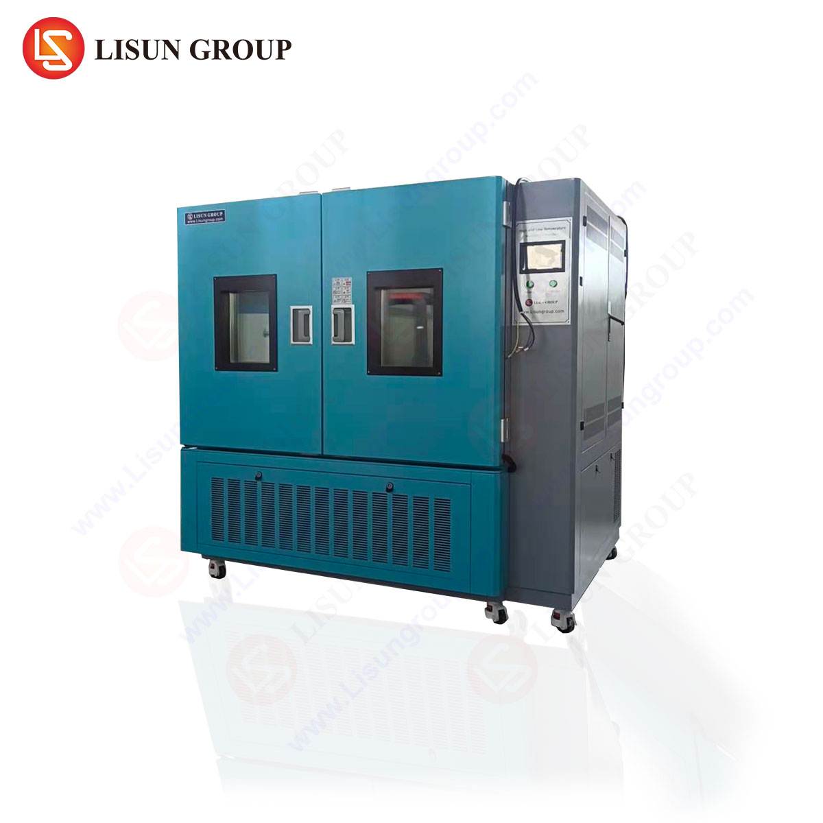
The HLST-500D Thermal Shock Test Chamber: Architecture for Precision
To execute reproducible and compliant thermal shock testing, specialized equipment is required. The LISUN HLST-500D Thermal Shock Test Chamber exemplifies a modern two-zone (basket transfer) system engineered for this precise function. Its architecture consists of three key zones: a high-temperature chamber, a low-temperature chamber, and a transition basket that shuttles the test specimen between them. This mechanical separation ensures that each climatic zone maintains exceptional temperature stability, uncontaminated by air from the opposing zone.
The HLST-500D operates on a defined test profile. The specimen is loaded onto the basket, which initially resides in a neutral position. The test commences with the basket transferring the load into the high-temperature chamber, where it dwells until the specimen’s internal temperature stabilizes at the setpoint (e.g., +150°C). Upon completion of the high-temperature dwell, the basket rapidly moves the specimen to the low-temperature chamber, where it stabilizes at the cold setpoint (e.g., -65°C). This cycle repeats for the programmed number of iterations. The system’s design minimizes transition time, a critical factor in applying the maximum thermal gradient stress.
Key Technical Specifications of the HLST-500D:
- Temperature Range: High Temperature Chamber: +60°C to +200°C; Low Temperature Chamber: -80°C to 0°C.
- Chamber Volume: 500 Liters (providing ample capacity for multiple products or large assemblies).
- Temperature Recovery Time: ≤5 minutes (from +150°C to -55°C or vice-versa, following the insertion of a specified aluminum heat mass).
- Temperature Fluctuation: ≤±0.5°C (ensuring setpoint stability during dwells).
- Basket Transfer Time: ≤10 seconds (maximizing the thermal shock effect).
- Control System: Digital programmable controller with data logging and real-time monitoring capabilities.
Industry-Specific Applications of Thermal Shock Validation
The utility of thermal shock testing spans the entire electronics ecosystem, each with unique requirements derived from end-use conditions.
- Automotive Electronics: Powertrain control modules, battery management systems (BMS), and LED headlamps are tested from -40°C to +125°C or beyond to simulate Arctic winters, desert operation, and heat-soak conditions. Solder joint integrity under these cycles is paramount for safety-critical systems.
- Aerospace and Aviation Components: Avionics boxes and satellite components undergo extreme profiles (e.g., -65°C to +125°C) to validate performance from ground operations to high-altitude flight and the thermal cycling of low-earth orbit.
- Lighting Fixtures: Outdoor LED luminaires and automotive lighting are subjected to shock tests to assess the resilience of the LED package, driver electronics, and lens-sealing interfaces against rain-induced thermal shocks.
- Telecommunications Equipment: Base station amplifiers and outdoor optical network units (ONUs) must withstand daily temperature swings. Testing ensures reliability of RF components and fiber optic transceivers.
- Medical Devices: Implantable electronics and portable diagnostic equipment are tested to stringent profiles to guarantee functionality after sterilization cycles (which can involve extreme temperatures) and during global transportation.
- Industrial Control Systems: PLCs and motor drives installed in unregulated environments, such as factories or substations, are validated for operational stability despite rapid ambient changes.
Correlative Analysis: Integrating Shock Testing into a Broader Test Regime
Thermal shock is rarely the sole determinant of reliability. Its true value is realized when its results are correlated with those from other tests. A comprehensive validation suite might follow a sequence such as:
- Highly Accelerated Life Test (HALT): To discover operational and destruct limits using combined, progressive stresses.
- Design Improvement: Implementation of corrective actions based on HALT findings.
- Qualification Testing: Execution of a battery of standardized tests, including:
- Thermal Shock (HLST-500D)
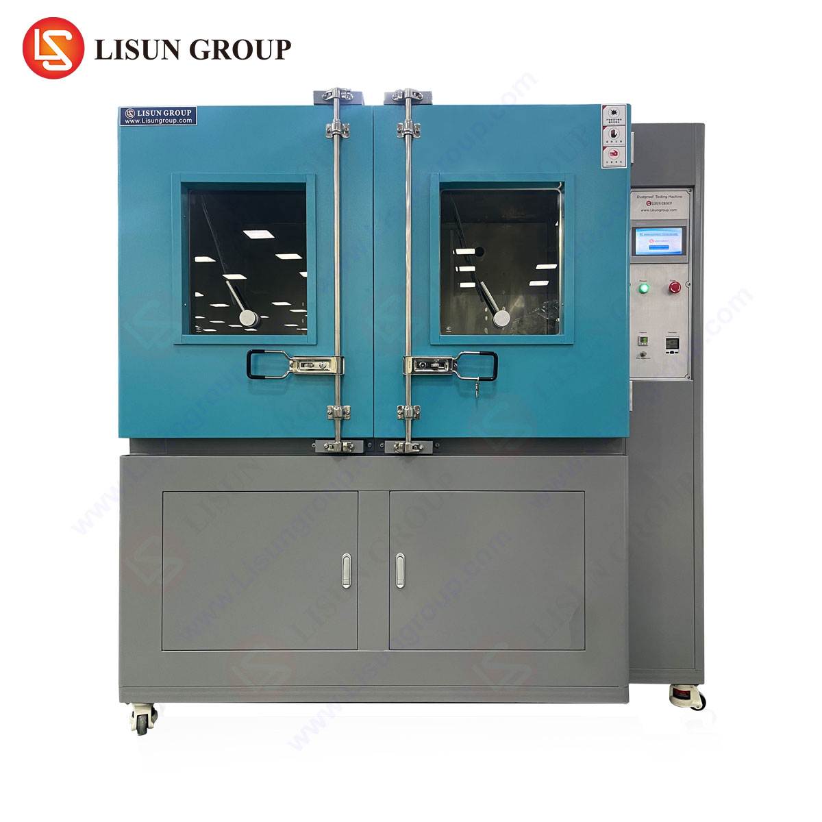
- Steady-State Temperature/Humidity (e.g., using a chamber like the GDJS-015B for 85°C/85%RH testing)
- Vibration and Mechanical Shock
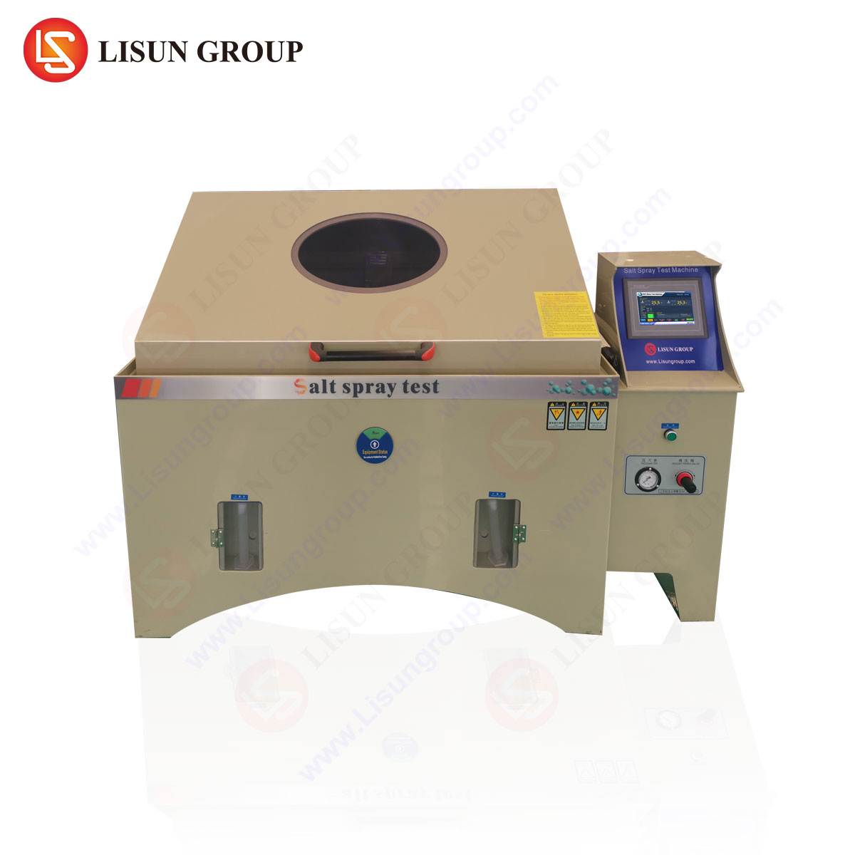
- Salt Spray / Corrosion
- Failure Analysis: Detailed physical and electrical examination of any failures from qualification testing to determine root cause.
- Reliability Demonstration Testing (RDT): A final, statistically significant test to demonstrate the achieved MTBF meets or exceeds requirements.
Data from thermal shock testing, particularly the cycle count to failure for a sample population, can be plotted using Weibull analysis to predict failure distribution and characteristic life under field conditions.
Methodological Considerations and Standards Compliance
Executing a valid thermal shock test requires careful planning. Specimen mounting must not inhibit free airflow or stress the unit unnaturally. Electrical monitoring during testing (in-situ monitoring) is often crucial to detect intermittent failures that may not be present at room temperature after the test. The choice of test profile must be aligned with the relevant industry standard, which dictates minimum/maximum temperatures, dwell times, and cycle counts. For example:
- Automotive: AEC-Q100 for integrated circuits.
- Consumer/Industrial: IEC 60068-2-14.
- Military/Aerospace: MIL-STD-883, MIL-STD-202, MIL-STD-810.
- Telecommunications: Telcordia GR-63-CORE.
The HLST-500D is engineered to facilitate compliance with these standards, offering the precision, repeatability, and data integrity required for certified testing laboratories and internal qualification departments.
Economic and Risk Mitigation Rationale for Rigorous Testing
The financial implications of reliability testing are overwhelmingly positive when viewed through the lens of total cost. The expense of advanced test equipment and dedicated laboratory time is dwarfed by the potential costs associated with field failures. These include warranty claims, massive recall campaigns, brand reputation damage, liability lawsuits (particularly in Automotive and Medical Device sectors), and loss of market share. Investing in a robust testing regimen, centered on capable equipment like the HLST-500D, transforms reliability from an uncertainty into a quantifiable, managed parameter. It enables front-loading of quality, ensuring problems are resolved on the engineering bench rather than in the customer’s hands. This proactive approach is a strategic imperative in today’s competitive, liability-conscious global marketplace.
FAQ Section
Q1: What is the primary functional difference between a thermal shock chamber (like the HLST-500D) and a standard temperature cycling chamber?
A: The key difference is the rate of temperature change. A thermal shock chamber achieves rapid transitions (often >15°C/min) by physically moving the test specimen between two extreme-temperature zones, maximizing thermal gradient stress. A standard temperature cycling chamber typically uses a single zone with a slower ramp rate, more suited for simulating gradual environmental changes rather than inducing severe thermo-mechanical fatigue.
Q2: For a new automotive sensor design, how do I determine the appropriate high and low temperature setpoints for thermal shock testing?
A: Setpoints are derived from the product’s specification sheet, which should define its operational and storage temperature ranges. They are also dictated by the relevant automotive qualification standard, such as AEC-Q100. A common profile for underhood components is -40°C to +125°C. The extremes are often set 5-10°C beyond the specified operational limits to incorporate a safety margin and accelerate testing.
Q3: Can the HLST-500D accommodate in-situ (live) electrical testing of devices during the thermal shock cycles?
A: Yes, this is a critical capability. The chamber is typically designed with electrical feed-through ports that allow connecting the device under test to external power supplies and measurement equipment. This enables continuous functional monitoring or periodic electrical parameter checks during the test, allowing engineers to detect intermittent failures that occur only at temperature extremes.
Q4: How is the “dwell time” at each temperature extreme determined for a valid test?
A: Dwell time is not arbitrary; it must be sufficient for the entire device under test, including its thermal mass, to stabilize at the target chamber air temperature. This is often determined by placing thermocouples on or within a representative sample to monitor its internal temperature. The dwell time is then set to exceed the measured stabilization time. Relevant testing standards often provide guidelines or formulas for calculating minimum dwell times based on product mass and composition.
Q5: What maintenance is critical for ensuring the long-term accuracy and reliability of a thermal shock test chamber?
A: Regular preventive maintenance is essential. Key tasks include: checking and calibrating temperature sensors (RTDs/thermocouples); inspecting and cleaning the air ducts and evaporators to ensure proper airflow and heat exchange; verifying the integrity and lubrication of the basket transfer mechanism; monitoring refrigerant gas pressure and compressor performance for the low-temperature zone; and checking the heaters and associated safety circuits in the high-temperature zone. A log of all maintenance and calibration activities is necessary for audit and quality assurance purposes.