


A Technical Analysis of SB1610 Test Pin B: Specifications, Calibration, and Application in Connector Safety Verification
Introduction
Within the rigorous framework of electrical safety testing for plugs, sockets, and appliance inlets, the integrity of the test apparatus is paramount. The SB1610 Test Pin B represents a critical, standardized component within this ecosystem, designed to verify a fundamental safety feature: the inaccessibility of live parts. This article provides a detailed technical examination of the SB1610 Test Pin B, its governing standards, operational principles, and its pivotal role within comprehensive testing systems, with particular focus on its implementation in the LISUN Gauges for Plugs and Sockets. The objective is to delineate the technical parameters and procedural necessities that ensure reproducible, standards-compliant safety assessments across global markets.
Defining the SB1610 Test Pin B and Its Governing Standards
The SB1610 Test Pin B is a calibrated, mechanical test probe specified within international safety standards, most notably IEC 61032, “Protection of persons and equipment by enclosures – Probes for verification.” Its primary, standardized designation is often “Test Probe B” or the “Standard Test Finger.” Its function is to simulate the possibility of human contact, specifically a child’s finger or a similar object, with hazardous live parts through openings in an enclosure, such as a socket outlet or an appliance connector.
The probe’s dimensions are not arbitrary; they are statistically derived from anthropomorphic data to represent a worst-case scenario for unintended access. The critical dimensions include a 12mm diameter spherical “finger” segment, a 20mm long jointed “knuckle” section of 50mm diameter, and a shield to prevent over-insertion. The SB1610 designation typically refers to a specific, commercially produced instantiation of this standardized probe, manufactured to exacting tolerances. Compliance with IEC 61032, and by reference standards such as IEC 60884-1 (plugs and sockets) and IEC 60320 (appliance couplers), is non-negotiable for any testing laboratory or manufacturer seeking product certification from bodies like UL, CSA, TÜV, or CCC.
Mechanical Tolerances and Material Considerations for the Probe
The efficacy of the SB1610 Test Pin B hinges on its precise physical construction. The materials selected must ensure dimensional stability, electrical insulation, and sufficient mechanical strength to withstand repeated use without deformation. Typically, the main body is machined from a rigid insulating material such as polyoxymethylene (POM) or a similar engineering polymer, chosen for its low moisture absorption and excellent creep resistance. The spherical tip and joint sections require a smooth finish, free of burrs or imperfections that could snag or provide an inaccurate assessment of an opening.
Tolerances for key dimensions are typically held within ±0.05mm for critical features like the 12mm sphere diameter and the 50mm knuckle diameter. The articulation of the joint must be free-moving yet without perceptible lateral play, allowing the probe to mimic the natural pivoting of a finger while maintaining a consistent geometric profile. Any deviation from these specifications risks generating false-positive or false-negative test results, potentially allowing an unsafe product to reach the market or unfairly failing a safe design.
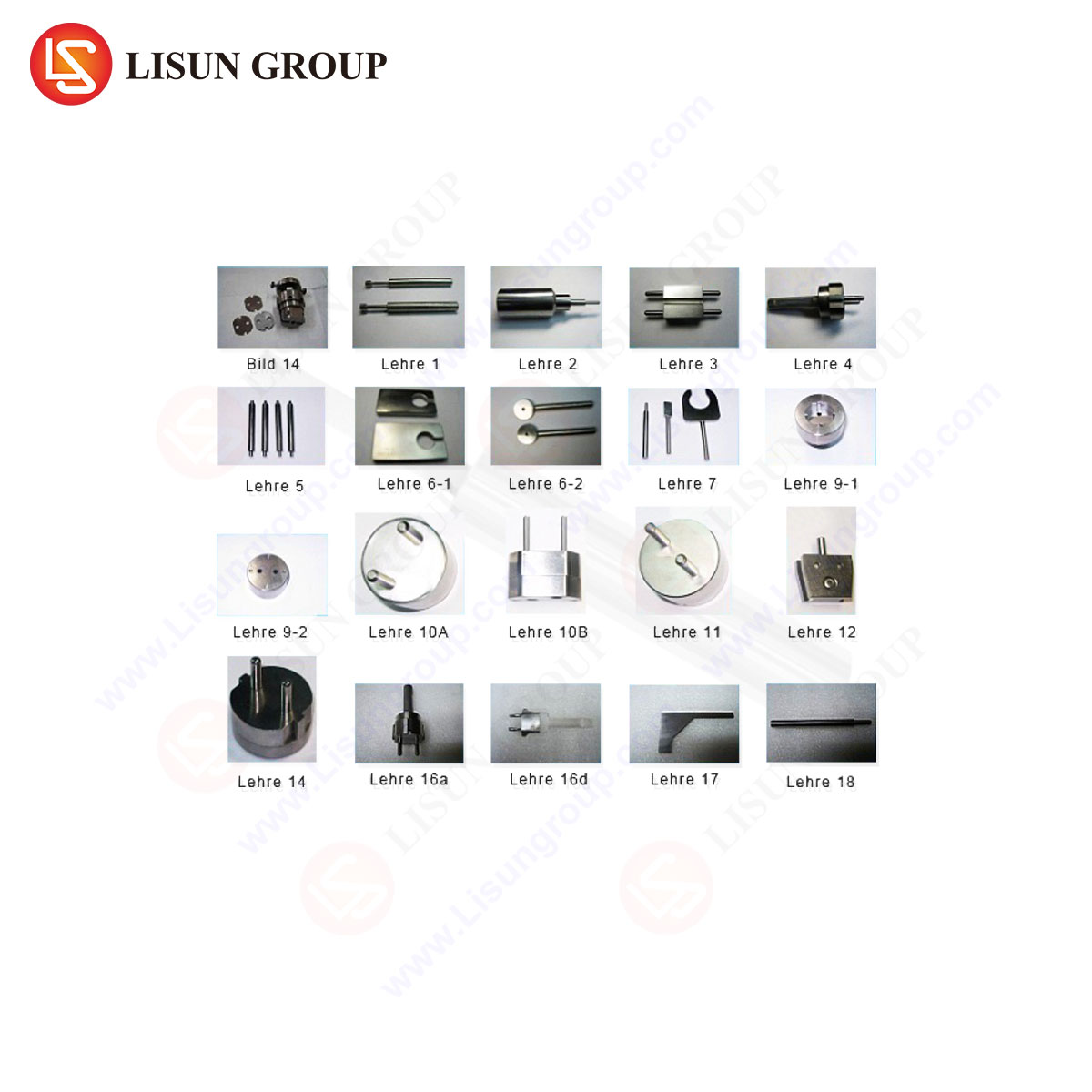
Integration within the LISUN Gauges for Plugs and Sockets System
The SB1610 Test Pin B is rarely employed in isolation. Its true utility is realized when integrated into a systematic testing apparatus. The LISUN Gauges for Plugs and Sockets system exemplifies this integrated approach. This system is a coordinated suite of calibrated gauges and fixtures designed to perform the full battery of mechanical and electrical safety tests mandated for connector products.
Within the LISUN system, the SB1610 probe is mounted in a calibrated, repeatable fixture that applies the specified force (typically 30 N ± 3 N as per IEC 61032) and articulation angles. The system ensures the probe is applied to every opening of the Device Under Test (DUT)—be it the shutter apertures of a socket, the pin entry of an appliance inlet, or ventilation slots on a plug body—in every possible orientation (straight-on and at angles up to 90° in any direction from the vertical). The LISUN apparatus often includes integrated electrical detection circuits. When the probe is inserted, a low-voltage (not less than 40V and not more than 50V) signal is passed through the probe. If contact is made with a live part or a part connected to a live part inside the enclosure, the circuit is completed, and a visual or audible indicator signals a test failure.
Testing Protocol and Failure Mode Analysis
The formal test procedure using the SB1610 within a system like LISUN’s follows a strict protocol. The DUT is energized at its rated voltage, or a simulated live part is installed. The probe is applied with the specified force to each external opening. The test is conducted with the probe in its straight position and then with it hinged at any angle to simulate probing. A failure is recorded if the indicator circuit is activated, signifying electrical contact, or if the probe physically contacts a live part, as verified by a subsequent dielectric strength test.
Analysis of failure modes is instructive. A common failure in socket outlets involves inadequate shutter mechanism design. The probe may defeat a poorly engineered shutter, making contact with the live contact inside. In appliance inlets, failures often stem from excessive clearance between the pin aperture and the inserted plug, allowing the probe to bypass insulation and touch a terminal. The data derived from SB1610 testing directly informs redesign efforts, focusing on reinforcing shutter spring forces, redesigning aperture geometries, or adding internal insulating barriers.
Industry Applications and Regulatory Implications
The application of SB1610 testing spans the entire electrical connector industry. Manufacturers of domestic and industrial socket-outlets, extension cord reels, power strips, appliance couplers (IEC 60320 C13/C14, C19/C20, etc.), and even luminaires with connector ports must all submit designs for this test. It is a mandatory component of type testing for safety certification.
Regulatory implications are significant. A product that fails the SB1610 test cannot receive the necessary safety marks (CE, UKCA, UL Listing, etc.) for legal sale in its target markets. Furthermore, surveillance testing by certification bodies and market surveillance authorities routinely includes SB1610 verification to ensure continued compliance of mass-produced items. The use of a traceably calibrated system like the LISUN Gauges ensures that test results are defensible and consistent across different testing locations and times, a critical factor in global supply chains.
Comparative Advantages of Automated and Semi-Automated Test Systems
While a basic SB1610 probe can be used manually, integrated systems offer distinct advantages. Manual testing is subject to operator variance in applied force and angle, potentially leading to inconsistent results. The LISUN system automates the application of force and the detection of contact, removing this variability. Furthermore, semi-automated fixtures can systematically index the probe across complex outlet faces, ensuring no aperture is missed. This repeatability enhances testing throughput in quality control laboratories and provides higher-confidence data for research and development teams iterating on prototype designs.
Another advantage lies in data logging. Advanced systems can record the exact location, force, and orientation of a failure, generating a report that is invaluable for forensic engineering analysis. This moves the process from a simple pass/fail to a diagnostic tool that pinpoints design weaknesses with high spatial resolution.
Maintenance, Calibration, and Traceability Requirements
Like all precision test equipment, the SB1610 Test Pin B and its hosting system require a formal maintenance and calibration regime. The probe itself must be periodically inspected for wear, particularly on the spherical tip and joint surfaces. Dimensional verification against master gauges or via coordinate measuring machine (CMM) inspection is essential, typically on an annual basis.
The force application mechanism of the fixture must be calibrated using a traceable force gauge. The electrical detection circuit must be verified for proper sensitivity and voltage. Calibration certificates for the entire system, traceable to national metrology institutes (e.g., NIST, NPL), are a prerequisite for accredited laboratory testing. The LISUN system is designed with these requirements in mind, featuring calibration access points and constructed from materials that ensure long-term stability between calibration cycles.
Conclusion
The SB1610 Test Pin B, as a physical embodiment of a key safety principle, serves as a gatekeeper in the development and production of electrical connectors. Its precise application, through integrated and calibrated systems such as the LISUN Gauges for Plugs and Sockets, transforms subjective safety assessments into objective, reproducible metrological data. This process is fundamental to mitigating the risk of electric shock, ensuring global regulatory compliance, and fostering continuous innovation in the design of safer electrical interfaces. As standards evolve and connector designs become more compact and complex, the role of precise, reliable test instrumentation will only grow in importance.
FAQ Section
Q1: How often should the SB1610 Test Pin B itself be calibrated or verified?
A1: The probe should undergo dimensional inspection at least annually, or more frequently if used in high-volume production testing. The inspection should verify critical diameters, lengths, and the smooth operation of the joint. A formal calibration certificate for the probe and its force application fixture is required for accredited laboratory work.
Q2: Can the SB1610 test be performed on a de-energized product?
A2: The standard test requires the live parts to be energized at rated voltage, or for a simulated live part to be installed and connected to the detection circuit. Testing a completely dead unit would not verify protection against actual live parts. However, a preliminary mechanical check can be done safely without power, but the final compliance test must be performed under electrically simulated conditions.
Q3: What is the significance of the 30 N force specified in the test?
A3: The 30 Newton force (approximately 3 kilograms of force) is derived from studies of the force a child might inadvertently apply. It represents a reasonable worst-case scenario for probing or pushing an object into an opening. Applying a standardized force ensures test results are comparable and not dependent on an individual operator’s strength.
Q4: Our product has a very small decorative opening less than 1mm wide. Does it still need to be tested with the SB1610?
A4: If the opening is rigid and its smallest dimension is less than 12mm, the full 12mm sphere of the SB1610 cannot enter. Standards typically provide rules for “small openings.” However, it may still be subject to testing with other specified probes from IEC 61032, such as the Test Probe 13 (a straight 1mm wire), to ensure a tool or wire cannot access live parts.
Q5: How does the LISUN system handle the testing of switched sockets or shutters that require simultaneous pin insertion?
A5: This is a critical aspect of socket testing. The LISUN system includes specialized fixtures and programmable sequences. For shutters that require simultaneous insertion of two pins (e.g., live and neutral) to open, the system can mount the SB1610 probe alongside standardized test pins. The sequence can apply the test pins first to open the shutter, then articulate the SB1610 probe to attempt to access the live contact, all while monitoring the electrical detection circuit.