


The Role of Standardized Finger Probes in Product Safety Compliance
The imperative to ensure user safety against electrical hazards is a foundational tenet of modern product design and manufacturing. Among the most critical tools for verifying compliance with international safety standards is the standardized test finger, also known as a test probe or test pin. These devices are not arbitrary implements but precisely engineered instruments designed to simulate human interaction with electrical equipment. Their application provides a quantifiable, repeatable method for assessing the effectiveness of enclosures, barriers, and insulation in preventing access to hazardous live parts. This article examines the technical specifications, operational principles, and broad industrial application of these probes, with particular reference to the implementation exemplified by the LISUN Test Finger.
Anthropomorphic Simulation in Safety Testing
The fundamental premise of the standard finger probe is anthropomorphic simulation. Safety standards, primarily the IEC 61032 standard “Protection of persons and equipment by enclosures,” define a series of probes intended to represent various parts of the human body. Probe 11, the “jointed test finger,” is the most ubiquitous, designed to simulate a child’s finger or an adult’s small finger. Its dimensions—a diameter of 12mm, a length of 80mm, and three joints with specific articulation limits—are derived from extensive anthropometric data. This probe is engineered to apply a standardized force, typically 10 N ± 0.5 N, to probe openings, seams, and gaps in equipment enclosures.
The testing objective is unambiguous: after application of the probe, the equipment must not permit contact with hazardous live parts, defined as parts carrying a voltage exceeding specified safety extra-low voltage (SELV) limits. Furthermore, the probe must not contact moving parts that could cause injury. The test is both a mechanical assessment of structural integrity and an electrical verification of safe separation. The precision of the probe’s construction is therefore paramount; even minor deviations in its dimensions, joint stiffness, or applied force can lead to non-representative test outcomes, potentially allowing unsafe products to market or falsely failing compliant designs.
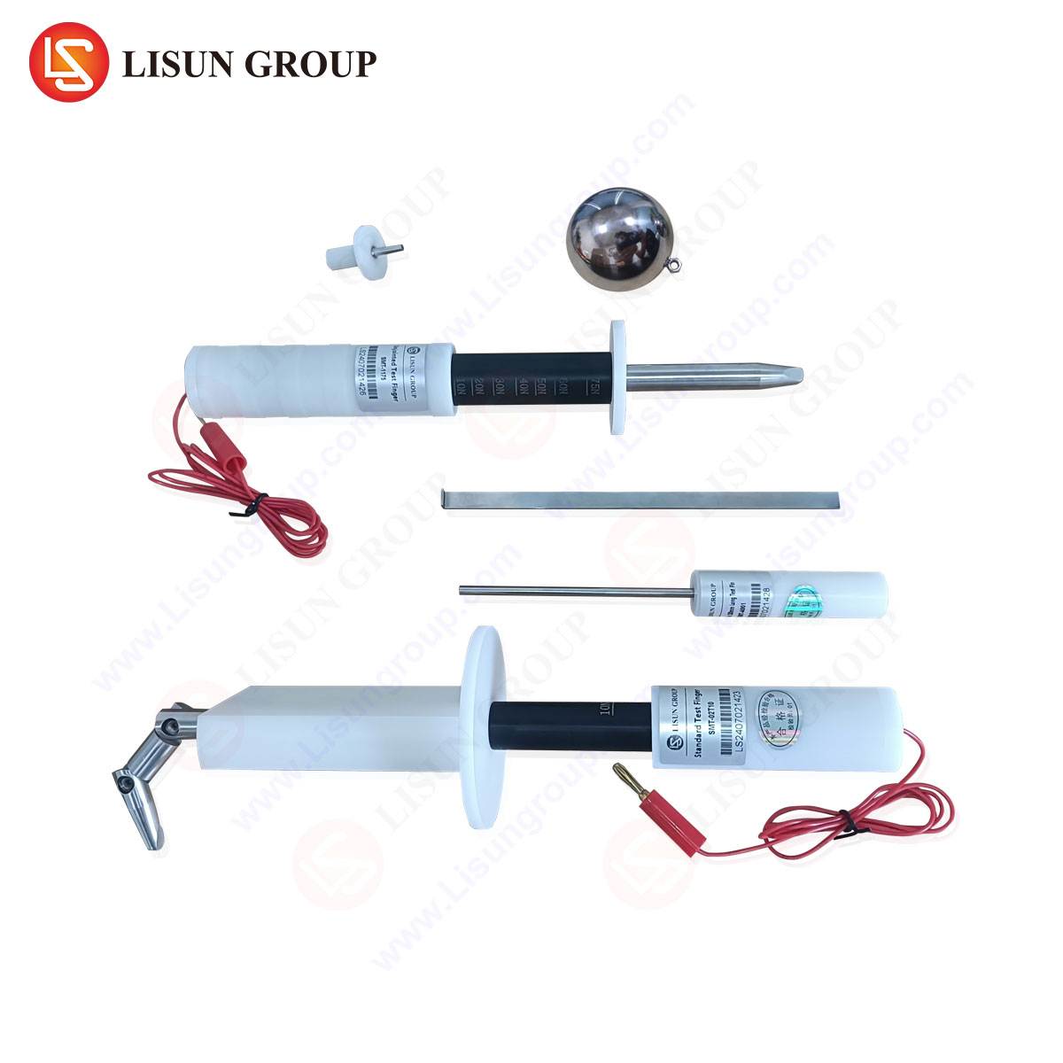
Technical Specifications and Calibration of the LISUN Test Finger
The efficacy of any test apparatus hinges on its adherence to defined specifications and its traceable calibration. The LISUN Test Finger (Probe 11) is manufactured to the exacting dimensional and mechanical requirements outlined in IEC 61032 and related standards such as IEC 60529 (IP Code) and UL 60950-1. Its construction typically utilizes a robust, insulating material such as high-impact polyamide, ensuring both durability and the necessary electrical insulation properties during testing.
Key specifications include:
- Dimensional Accuracy: A diameter of 12.0 mm (+0.0 mm, -0.1 mm) over its 80 mm length, with joint centers precisely spaced to allow for the correct articulation.
- Articulation Range: The two proximal joints are designed to articulate 90° ±5° from the straight axis in the same plane and 180° ±10° in all directions, mimicking the natural flexibility of a finger.
- Applied Force: The probe assembly is configured to apply a consistent 10 Newton force. This is often achieved through a calibrated spring mechanism or deadweight system integrated into the test apparatus.
- Electrical Indicator: A critical component is the “touch indicator” circuit. A metallic foil or strip is applied to the surface of the probe, connected via a low-voltage (e.g., 40-50V) circuit with a visual or audible indicator (typically an LED or buzzer). Contact with a live part completes this circuit, providing an unambiguous fail signal.
Regular calibration against reference gauges and force meters is essential to maintain the probe’s metrological integrity. Competitive advantages of a system like the LISUN probe often lie in its comprehensive calibration certification, which provides traceability to national standards, and its ruggedized design that resists deformation over repeated use—a common point of failure for lower-quality probes that can compromise long-term testing consistency.
Application Across Industrial Sectors
The application of standard finger probes is virtually universal across industries manufacturing equipment with accessible enclosures and electrical components.
- Electrical and Electronic Equipment & Household Appliances: This is the primary domain. Testers use the probe to verify that openings for ventilation, cable ports, or control interfaces on devices like power supplies, desktop computers, refrigerators, and washing machines prevent finger access to mains-voltage wiring or motor assemblies.
- Automotive Electronics: As vehicles incorporate more high-voltage systems (e.g., in electric vehicle traction batteries and charging ports) and user-accessible infotainment units, probe testing ensures that serviceable compartments and passenger-accessible areas are safe from accidental contact with live terminals.
- Lighting Fixtures: For both commercial and residential fixtures, the probe checks gaps between the diffuser and body, entry points for wiring, and the accessibility of lamp terminals after bulb replacement.
- Industrial Control Systems: Enclosures for programmable logic controllers (PLCs), motor drives, and human-machine interfaces (HMIs) are probed to confirm that panel seals and door gaps protect operators from internal power buses.
- Medical Devices: Patient safety is critical. Probes test bedside monitors, diagnostic equipment, and therapeutic devices to ensure that even if a casing is cracked or a seal compromised, no hazardous touch points are exposed.
- Aerospace and Aviation Components: In-flight entertainment systems, galley equipment, and control panel enclosures are tested to rigorous aerospace standards, often incorporating probe tests to verify integrity under vibration and pressure differentials.
- Electrical Components: Directly applied to products like switches, sockets, and connectors, the probe verifies that live contacts are recessed or shielded sufficiently to prevent a finger from making electrical contact.
- Toy and Children’s Products Industry: Given the specific simulation of a child’s finger, this test is mandatory. It ensures battery compartments, speaker grilles, and joints in electronic toys cannot trap a finger or allow contact with battery terminals or circuit boards.
Interpreting Test Results and Failure Modes
A successful test result is characterized by the non-illumination of the probe’s indicator throughout the systematic application of the probe to every potential access point. The test procedure is methodical, requiring the probe to be articulated and pushed into openings with the specified force. Failure modes are typically categorized as follows:
- Direct Electrical Contact: The probe’s indicator circuit is activated, signifying the metal foil has contacted a live part. This is a clear and critical failure.
- Indirect Contact via a Conductive Object: The probe may push a loose wire, a detached screw, or other conductive debris into contact with a live part, also triggering the indicator. This highlights design flaws in internal wire routing or securing methods.
- Compromise of Safety Distances: While perhaps not causing immediate contact, the probe may deform an internal barrier or insulation, reducing creepage and clearance distances below the minimum required for the working voltage. This often necessitates further investigation, possibly involving a dielectric strength test.
The data generated is binary (pass/fail) but profoundly significant. It forms a key piece of objective evidence in a product’s technical construction file, demonstrating due diligence in risk assessment and mitigation for regulatory bodies like OSHA, the EU’s notified bodies, and various national certification organizations.
Integration Within a Broader Safety Testing Regimen
The jointed test finger probe is rarely used in isolation. It is a component within a larger suite of tests for enclosure protection (IP Code), mechanical strength, and electrical safety. For example, it is frequently employed after or in conjunction with:
- Impact Tests: To ensure an enclosure crack caused by a mechanical impact does not create a probe-accessible opening.
- Stress Relief Tests: For flexible cord entries, to verify that pulling on a power cord does not displace internal parts to create a hazard.
- Thermal Conditioning: To ensure plastic enclosures do not warp or soften under operating temperatures to a degree that creates an openable gap.
The sequence of testing is logically structured: mechanical and environmental tests that could weaken the enclosure are performed first, followed by the probe test to verify that safety has not been compromised. The LISUN Test Probe system is often designed for integration into such workflows, with mounting fixtures and accessories that allow for consistent, repeatable application in a laboratory setting.
Conclusion
Standard finger probes represent a critical nexus between theoretical safety design and practical, enforceable compliance. By providing an objective, repeatable simulation of a common human action, they translate abstract safety principles into a concrete, actionable test. The precision and reliability of the test equipment, such as the calibrated LISUN Test Pin system, are therefore not merely a matter of convenience but a fundamental requirement for ensuring global product safety, facilitating international trade, and, ultimately, protecting end-users from electrical harm across a vast spectrum of technologies and industries. Their continued evolution will parallel advancements in miniaturization and new human-equipment interaction paradigms, ensuring safety standards keep pace with innovation.
Frequently Asked Questions (FAQ)
Q1: Can the standard test finger (IEC 61032 Probe 11) be used for both IP code testing (IEC 60529) and basic safety testing (e.g., IEC 62368-1)?
Yes, it is a dual-purpose tool. In IP code testing, it is used to verify the first numeral (protection against solid objects, specifically “protection from tools and wires greater than 12.5mm in diameter” and “protection from contact with fingers”). In basic safety standards like IEC 62368-1, it is applied to verify that enclosures prevent access to hazardous live parts, which is a separate but related requirement. The same physical probe is used, though the test procedure and acceptance criteria are defined by the respective standard.
Q2: How often should a test finger probe be calibrated, and what does calibration involve?
A typical calibration interval is 12 months, or following any event that could cause damage (e.g., a drop). Calibration involves verifying: 1) Dimensional accuracy: Using precision micrometers and gauges to confirm diameter, length, and joint spacing. 2) Articulation: Checking that the joint angles fall within the specified tolerance bands. 3) Applied force: Measuring the force exerted by the probe’s mechanism using a calibrated force gauge. A full calibration certificate should document these measurements with traceability to national standards.
Q3: Our product has a flexible rubber diaphragm over a button. Is the test finger applied with enough force to deform and penetrate this diaphragm?
Yes, the test is deliberately severe. The 10 N force is applied to the probe, and it is articulated in all possible ways. If the flexible diaphragm deforms under this force and articulation to such an extent that the metal foil on the probe could contact a live part behind it, the product would fail the test. The design must account for this predictable probing action.
Q4: What is the significance of the “touch indicator” voltage (often 40-50V)? Why isn’t it the product’s actual operating voltage?
The indicator circuit uses a safety extra-low voltage (SELV) to avoid the risk of the test apparatus itself becoming a hazard. Its purpose is solely to detect electrical continuity, not to test dielectric withstand. A voltage of 40-50V is high enough to reliably indicate contact through potential surface contaminants but is safely isolated from mains. The product’s own operating voltage is tested separately in a dielectric strength (hipot) test.
Q5: For very small openings, is a different probe used?
Yes. IEC 61032 defines multiple probes. Alongside the jointed test finger (Probe 11), common probes include the “test probe” (Probe 12, a rigid 3mm diameter wire to simulate tools), the “test pin” (Probe 13, a 1mm diameter wire for very small openings), and the “test sphere” (Probe 18, a 12.5mm sphere). The appropriate probe is selected based on the specific hazard and accessibility criteria in the applicable product safety standard.