


A Technical Compliance Gauge for Cover Contour Testing: Ensuring Safety and Interoperability in Plugs and Sockets
Introduction: The Critical Role of Dimensional Integrity in Electrical Safety
The global proliferation of electrical devices, coupled with the increasing density of power outlets in residential, commercial, and industrial environments, places unprecedented emphasis on the fundamental safety of plugs and sockets. While electrical testing of insulation resistance, dielectric strength, and grounding continuity are well-established protocols, the foundational mechanical integrity of these components is equally vital. A plug must insert and withdraw with appropriate force, establish secure electrical contact, and, crucially, prevent access to live parts under normal use or foreseeable misuse. The contour of a socket’s cover—the faceplate or bezel surrounding the apertures—plays a pivotal, yet often under-scrutinized, role in this safety matrix. Deviations in this contour can lead to excessive gaps, compromising the protective shuttering mechanisms mandated by modern safety standards, or creating pinch points that damage plug pins. Consequently, the implementation of a precise, repeatable, and standardized Technical Compliance Gauge for cover contour testing has become an indispensable element in the manufacturing quality assurance and type-testing regimen for sockets and socket assemblies.
Defining the Cover Contour and Its Functional Imperatives
The cover contour refers to the precise three-dimensional geometry of the socket’s front surface, specifically the profile surrounding and leading into the pin insertion apertures. Its design is not merely aesthetic; it is a critical engineered interface governed by stringent clauses within international standards such as IEC 60884-1, BS 1363, and AS/NZS 3112. The primary functional imperatives of this contour are threefold. First, it must guide the plug pins accurately into the apertures without binding or scuffing, which could deform the pins or damage the plug’s insulation. Second, it must maintain specified minimum distances (creepage and clearance) from live parts, ensuring that even a partially inserted plug or a foreign object cannot easily bridge a conductive path. Third, and most critically for shuttered sockets, the contour must interact flawlessly with the plug’s earth pin (or other shutter-actuation mechanism) to allow the shutters to open smoothly, while ensuring they close fully and securely when the plug is removed, thereby denying access to energized contacts.
The Metrological Challenge: Quantifying Complex Geometries Against Standards
Traditional measurement techniques using calipers, height gauges, or even coordinate measuring machines (CMMs) are often ill-suited for efficient, high-volume verification of cover contours. While CMMs offer high accuracy, they are slow, require specialized programming and operation, and provide data that requires interpretation against often complex, composite dimensional requirements outlined in standards. The need is for a pass/fail or go/no-go gauge that embodies the worst-case permissible geometry as defined by the standard. This gauge, often called a contour gauge or template gauge, provides a direct physical simulation of the maximum allowable intrusion or minimum required clearance. The challenge lies in manufacturing these gauges with micron-level precision, from materials with appropriate wear resistance and thermal stability, and ensuring they correctly encapsulate the often-complex compound requirements of the standard—which may involve simultaneous checks of multiple radii, angles, and step profiles.
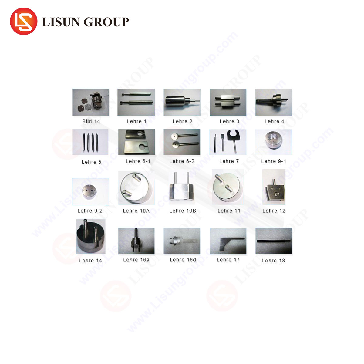
The LISUN Gauges for Plugs and Sockets: A Systemized Approach to Compliance Verification
To address this metrological challenge systematically, manufacturers and testing laboratories employ specialized gauge systems. The LISUN series of Technical Compliance Gauges for Plugs and Sockets represents a comprehensive, standards-specific solution. These gauges are not universal tools but are meticulously designed and manufactured to the exact dimensional limits prescribed for specific socket types and standards. For cover contour testing, the LISUN system typically includes a dedicated contour test gauge, often designated with a reference such as “Gauge 12” for BS 1363 or its equivalent for other standards.
The principle of operation is one of simulated interference. The gauge, constructed from hardened tool steel or similarly durable, dimensionally stable material, is applied to the socket cover under a specified force or through a defined manipulation. The test has two potential outcomes. A “pass” is achieved if the gauge cannot enter or make contact with prohibited zones around the apertures, demonstrating that the socket contour provides adequate protection. A “fail” occurs if the gauge can be inserted or makes contact, indicating a non-conformity that could compromise safety—for instance, a recess that is too deep, a radius that is too small creating a potential pinch point, or an overall profile that would allow a child’s finger or a thin object to probe too close to live parts.
Specifications and Tolerances in Gauge Manufacturing
The efficacy of a compliance gauge is entirely dependent on the precision of its own manufacture. LISUN gauges are characterized by exceptionally tight tolerances, typically in the range of ±0.01 mm to ±0.02 mm for critical features. The materials selected, such as case-hardened steel or stainless steel, are chosen for their resistance to abrasion from repeated use against plastic socket faces and their low coefficient of thermal expansion to maintain accuracy across different environmental conditions in labs and factories. Surface finish is also critical; a finely lapped surface ensures smooth operation without binding and prevents false failures due to friction. Each gauge is accompanied by a calibration certificate traceable to national metrological institutes, documenting its as-built dimensions against the theoretical standard requirements. This traceability is non-negotiable for accredited testing laboratories and for manufacturers seeking to demonstrate due diligence in their quality processes.
Integration into Type Testing and Production Line Quality Assurance
The application of cover contour gauges spans the product lifecycle. During type testing—the comprehensive evaluation of a product design prior to mass production—the gauge is used to verify that the design, as embodied in the tooling for the socket cover, meets the standard. This is a definitive pass/fail criterion; a design that fails the contour test cannot be certified.
In production line quality assurance, the gauge serves as a rapid audit tool. While 100% inspection of every socket with a contour gauge may not be feasible on high-speed assembly lines, it is a cornerstone of statistical process control (SPC). Regularly scheduled sampling—for example, checking one unit per hour or per batch—provides immediate feedback on the molding process. A trend of gauges beginning to fit where they should not can indicate tool wear in the injection molding die, variations in material shrinkage, or misalignment in assembly. This allows for corrective action before non-conforming products are produced in large quantities.
Industry Use Cases: From Manufacturer to Certification Body
The stakeholders for cover contour testing are diverse. Socket and accessory manufacturers use these gauges in their in-house QA labs and on the factory floor to ensure product conformity and reduce the risk of costly recalls or certification failures. Third-party testing and certification bodies (e.g., those providing UL, VDE, or ASTA marks) rely on these gauges as mandated test equipment during their assessment. Their gauges must be impeccably calibrated, as their verdict carries legal and commercial weight. National standards authorities and regulators may use them during market surveillance activities to verify that products on shelves continue to comply with safety regulations. Finally, large purchasers and specifiers, such as construction firms or facility management companies for major projects, may employ gauges for incoming inspection of electrical accessories, ensuring the installed base meets the specified safety level.
Competitive Advantages of a Dedicated Gauge System
Utilizing a purpose-built system like the LISUN gauges offers distinct advantages over ad-hoc measurement methods. Speed and Efficiency: A test can be completed in seconds by a production line operator, requiring minimal training. Unambiguous Results: The go/no-go outcome eliminates interpretation errors associated with reading numerical values from an instrument. Direct Standards Compliance: The gauge physically embodies the standard’s requirements, ensuring the test is exactly what the standard’s authors intended. Durability and Consistency: Professionally manufactured gauges withstand thousands of cycles without degradation, providing consistent results over time and across multiple users or locations. Risk Mitigation: By providing a clear, standardized check, they directly mitigate the risk of shipping non-compliant products that could lead to safety incidents, liability claims, and brand damage.
Beyond the Gauge: Correlating Contour with Performance Testing
It is important to view contour testing not in isolation, but as part of a holistic safety evaluation. A socket that passes the contour gauge must still undergo a battery of related tests. For example, the pin insertion/withdrawal force test correlates directly with contour; an overly tight or misaligned entry can cause excessive insertion force. The shutter robustness and durability test (e.g., 5,000 cycles of operation) relies on a correct contour to ensure the shutters are not jammed or prematurely worn by misaligned plug entry. Furthermore, the resistance to heat test can be impacted; a poor contour causing high friction during plug insertion can generate localized heat. Thus, the contour gauge is a first, critical check that enables subsequent performance tests to be conducted on a dimensionally valid sample.
Conclusion: The Unseen Guardian of Electrical Interface Safety
The Technical Compliance Gauge for Cover Contour Testing is a paragon of applied metrology—a simple, robust tool that translates pages of complex dimensional specifications into a single, definitive physical check. In an industry where safety is paramount and non-compliance carries severe consequences, such tools are indispensable. Systems like the LISUN Gauges for Plugs and Sockets formalize this essential verification step, providing manufacturers, testers, and regulators with the confidence that the most visible and tactile part of a socket—its face—is engineered not just for form, but fundamentally for safety. By ensuring the precise geometry of the cover contour, these gauges silently uphold the barriers that protect users from electrical hazards, proving that in safety-critical component manufacturing, the most effective solutions are often those that provide unambiguous answers to critical questions of fit and form.
Frequently Asked Questions (FAQ)
Q1: How often should a cover contour gauge be calibrated in a production environment?
A: Calibration frequency depends on usage intensity and quality system requirements. For high-volume daily use in production, an annual calibration is typical, with intermediate checks using a master reference socket or gauge block. Accreditation bodies like ISO/IEC 17025 often mandate a defined calibration schedule with traceable certificates. Any physical damage or suspected wear should trigger an immediate recalibration.
Q2: Can one universal contour gauge be used for sockets designed to different national standards?
A: No. The dimensional requirements for cover contours, including aperture surround dimensions, radii, and recess depths, are specific to each standard (e.g., BS 1363, IEC Type F, AS/NZS 3112). A gauge is only valid for the socket type it was designed to assess. Using an incorrect gauge will yield meaningless and potentially unsafe results.
Q3: If a socket fails the contour gauge test but a plug inserts smoothly, is it still a safety concern?
A: Yes, absolutely. The gauge tests worst-case scenarios and dimensional limits that a standard plug may not replicate. A failure indicates the socket does not meet the prescribed safety geometry, which could compromise shuttering function, reduce creepage distances, or allow access with non-standard objects. Compliance with the standard, not just functional compatibility with a specific plug, is the mandatory requirement.
Q4: What are the most common manufacturing defects that cause a contour test failure?
A: Typical root causes include wear or damage to the injection molding tool, leading to flashed edges or incorrect radii; excessive material shrinkage due to variations in process parameters like temperature or cooling time; and misalignment during the assembly of the socket face to the underlying mechanism, creating uneven gaps or offsets.
Q5: Are there digital or automated versions of the manual contour gauge?
A: While manual gauges remain the standard for portability and cost-effectiveness, automated vision inspection systems are increasingly used on high-speed production lines. These systems use high-resolution cameras and software to measure the contour against a digital template. However, the manual gauge remains the definitive reference for type testing and for calibrating such automated systems, as it is the physical embodiment of the standard’s requirement.