


Methodologies and Technological Considerations in Environmental Stress Screening for Modern Electronics
The relentless miniaturization and increased functional complexity of modern electronic and electromechanical systems have precipitated a concomitant rise in their sensitivity to environmental stressors. Reliability engineering, therefore, necessitates rigorous validation under controlled, accelerated conditions that simulate years of operational life within a compressed timeframe. Temperature humidity chambers, also known as environmental test chambers or climatic chambers, serve as the cornerstone apparatus for this critical validation process. This article examines the technological landscape of temperature humidity chamber manufacturers, delineates core testing principles, and analyzes the application of specific chamber types across diverse industrial sectors, with particular focus on a representative advanced model.
The Engineering Imperative for Controlled Environmental Stress Testing
All materials exhibit intrinsic physical responses to thermal and hygrometric fluctuations. In electronic assemblies, these responses manifest as coefficient of thermal expansion (CTE) mismatches between dissimilar materials, leading to mechanical fatigue at solder joints, underfills, and wire bonds. Concurrently, humidity ingress can catalyze electrochemical migration, leading to dendritic growth and short circuits, or promote galvanic corrosion at dissimilar metal interfaces. The primary objective of environmental stress screening (ESS) is not merely to verify operation within a specification window but to identify latent defects, quantify performance margins, and predict field failure rates. Standards bodies such as the International Electrotechnical Commission (IEC), particularly with standards like IEC 60068-2-1 (cold), IEC 60068-2-2 (dry heat), and IEC 60068-2-30 (damp heat, cyclic), provide standardized test profiles that form the basis for chamber programming and industry-acceptable validation protocols.
Architectural Taxonomy of Modern Test Chamber Manufacturers
The market for environmental test equipment is stratified, with companies specializing across a spectrum of capabilities. At one end, manufacturers produce highly standardized, benchtop units for routine quality checks. At the other, fully customized, walk-in chambers are engineered for testing entire automotive subsystems or aerospace assemblies. Leading global entities often distinguish themselves through proprietary refrigeration systems, advanced humidity generation techniques, and sophisticated control algorithms that ensure chamber uniformity and setpoint fidelity. Key differentiators include temperature transition rates, humidity range (often extending to 98% RH or with low dew point capabilities for dry testing), and the integration of ancillary stress factors such as vibration (highly combined environmental testing) or UV radiation. Data acquisition integrity, remote monitoring capabilities, and compliance with regulatory standards for calibration (e.g., ISO/IEC 17025) are further critical selection criteria for procurement teams in highly regulated industries.
Operational Principles of Combined Temperature and Humidity Simulation
A fundamental chamber consists of an insulated workspace, a refrigeration system for cooling and dehumidification, an electrical heater for temperature elevation, and a humidity generation system—typically a steam generator or ultrasonic atomizer. Precise control is achieved through a cascade of feedback loops. A platinum resistance thermometer (PRT) or thermocouple network provides temperature data to the programmable logic controller (PLC), which modulates compressor, heater, and liquid injection valves. Humidity, measured via capacitive polymer sensors or chilled-mirror hygrometers, is controlled by balancing the latent heat of vaporization from humidity injection against the sensible heat removal of the refrigeration coil. Advanced chambers employ separate cooling circuits for the workspace and the air-handling unit to prevent undesirable dehumidification during temperature ramp-up phases, a common pitfall in less sophisticated designs. The uniformity and stability of these parameters, defined as the spatial and temporal deviations from the setpoint, are paramount metrics of chamber performance.
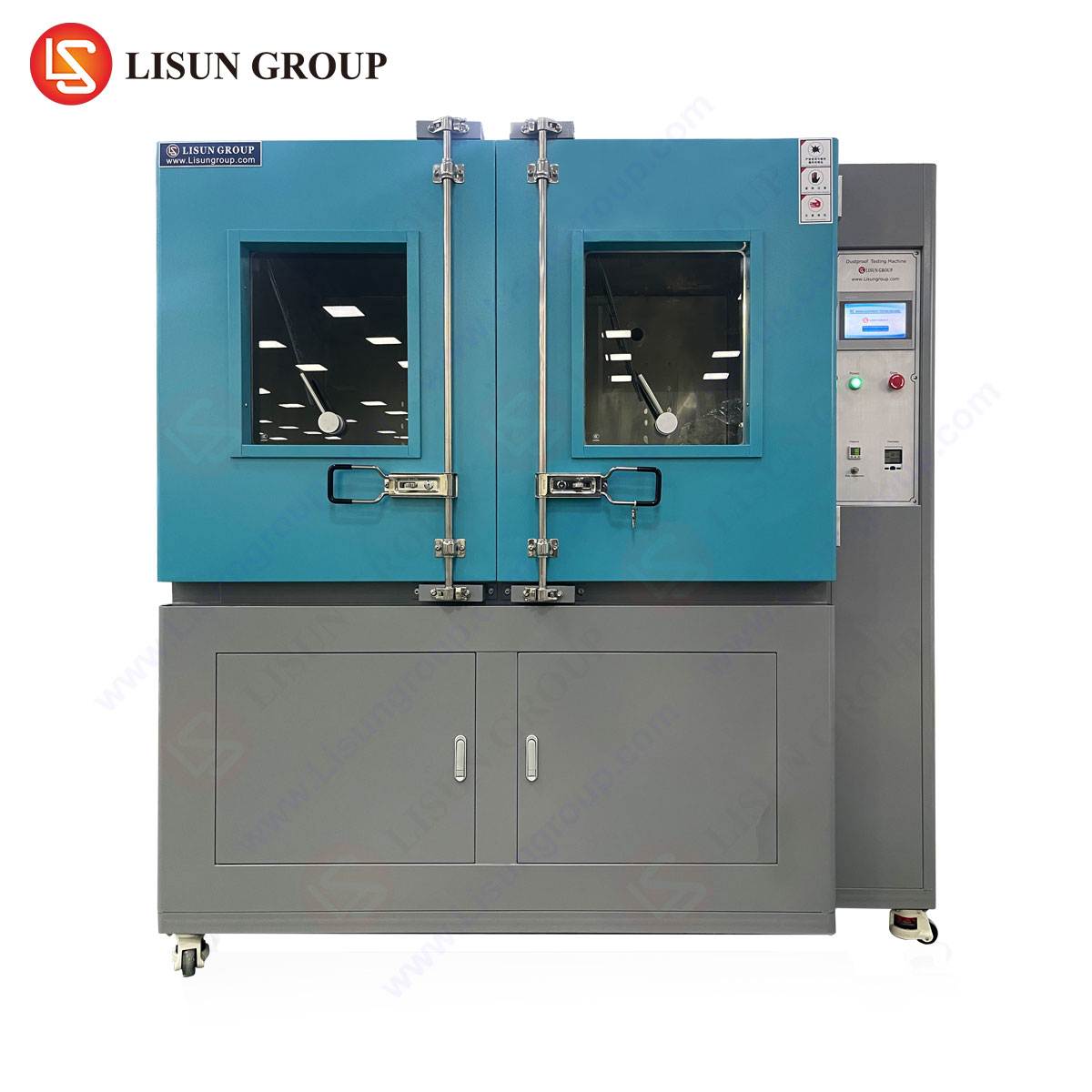
Analysis of the GDJS-015B Temperature Humidity Test Chamber for Component-Level Validation
The LISUN GDJS-015B represents a class of compact yet fully featured chambers designed for component and small assembly testing. Its specifications are engineered to meet the exacting requirements of standard compliance testing across multiple industries.
Key Technical Specifications:
- Temperature Range: -70°C to +150°C
- Humidity Range: 20% to 98% RH
- Workspace Volume: 150 Liters
- Heating Rate: Approx. 3°C/min (ambient to +150°C, nominal)
- Cooling Rate: Approx. 1°C/min (ambient to -70°C, nominal)
- Temperature Fluctuation: ≤±0.5°C
- Temperature Uniformity: ≤±2.0°C
- Humidity Deviation: ±2.0% RH (≥75% RH conditions)
- Refrigeration System: Cascade refrigeration with dual compressors (e.g., high-stage and low-stage)
- Controller: Digital, programmable touchscreen interface with RS-485 or USB connectivity for data logging.
Testing Principles Embodied: The chamber’s extended temperature range, spanning -70°C to +150°C, enables comprehensive testing from extreme cold start conditions to high-temperature operational limits. The cascade refrigeration system is critical for reliably achieving and maintaining sub-ambient temperatures while managing the latent loads introduced during humidity testing. The specified rates of change are deliberate; they are sufficiently rapid to induce thermal stress without causing non-representative thermal shock, making the chamber ideal for steady-state dwell tests and moderated thermal cycling per standards like IEC 60068-2-14 (Change of Temperature).
Industry Use Cases and Applications:
- Electrical Components & Automotive Electronics: Testing connectors, sensors, and engine control units (ECUs) for condensation resistance and thermal cycling endurance.
- Telecommunications Equipment: Validating optical transceivers, small cell enclosures, and fiber optic connectors against damp heat cyclic tests to simulate long-term deployment.
- Medical Devices: Accelerated aging of diagnostic equipment sub-assemblies and battery-powered portable devices to establish shelf life and operational reliability.
- Lighting Fixtures: Evaluating LED drivers and sealed luminaires for performance under high humidity and temperature cycling to prevent lumen depreciation and corrosion.
- Consumer Electronics & Office Equipment: Testing the robustness of printed circuit board assemblies (PCBAs) within smartphones, laptops, and printers against environmental stress.
Competitive Advantages: The primary advantage of a chamber like the GDJS-015B lies in its balanced performance envelope within a compact footprint. The cascade system provides laboratory-grade low-temperature performance often absent in single-compressor chambers of similar size. Its control stability (±0.5°C, ±2.0% RH) ensures data integrity for compliance reporting. Furthermore, its programmability allows for the creation of complex multi-segment profiles that can sequentially test a product’s response to storage, operational, and condensation scenarios.
Interpreting Chamber Specifications for Real-World Testing Scenarios
A procurement decision must align chamber capabilities with the intended test profiles. For example, testing an aerospace component to DO-160G Section 4.0 (Temperature and Altitude) requires an extremely low-temperature capability and potentially a vacuum system, which a standard chamber does not provide. Conversely, testing household appliances to IEC 60335-1 primarily involves damp heat and steady-state temperature tests well within the GDJS-015B’s range. The cooling and heating rates are particularly crucial. A chamber with a 10°C/min ramp rate may be marketed as “faster,” but many component standards, such as those for automotive electronics (e.g., AEC-Q100), specify maximum ramp rates (e.g., 3°C/min) to avoid unrealistic material stresses. Therefore, a chamber with a controlled, moderate ramp like the GDJS-015B may offer more standardized and representative testing than one with uncontrolled aggressive transitions.
Integration of Environmental Testing into Product Development Lifecycles
Environmental testing is not a singular gate at the end of development but a phased activity. During the design verification phase, chambers like the GDJS-015B are used for margin testing (operating beyond specification limits) and failure mode discovery. In production validation, they are used for Highly Accelerated Life Testing (HALT) to identify weak links, and in qualification, for precise compliance testing to published standards. Finally, in ongoing quality assurance, chambers perform routine lot sampling tests. The data derived feeds back into design iterations, material selection, and process controls, creating a reliability feedback loop. The connectivity and logging features of modern chambers are essential for tracing test conditions directly to unit under test (UUT) performance data, a requirement for audit trails in medical (ISO 13485) and automotive (IATF 16949) industries.
Future Trajectories in Stress Testing Technology
The evolution of test chambers is being shaped by several convergent trends. The Internet of Things (IoT) enables remote, real-time monitoring of chamber conditions and UUT performance from anywhere in the world. Machine learning algorithms are beginning to be applied to test data to predict failure trends and optimize test profile durations, moving from pass/fail results to predictive reliability analytics. Furthermore, as the global supply chain faces scrutiny, there is increased demand for chambers that can accurately replicate the specific climatic conditions of diverse geographic markets—from tropical high-heat, high-humidity environments to arid desert climates—within a single test profile. Sustainability concerns are also driving the adoption of low-global-warming-potential (GWP) refrigerants and energy-efficient system designs in new chamber development.
Frequently Asked Questions (FAQ)
Q1: What is the significance of the cascade refrigeration system in a chamber like the GDJS-015B?
A cascade system uses two separate refrigeration circuits. The first stage cools the condenser of the second stage, which in turn cools the chamber workspace. This architecture is necessary to achieve and maintain temperatures significantly below -40°C efficiently and reliably, as a single-stage compressor struggles with the increasing pressure ratio and volumetric efficiency losses at very low evaporator temperatures.
Q2: How do I determine if the chamber’s humidity range is suitable for testing my product to a specific standard?
Cross-reference the standard’s test conditions with the chamber’s specifications. For instance, IEC 60068-2-78 (Cab: Damp Heat, Steady State) commonly specifies 85°C/85% RH. The GDJS-015B’s range of 20% to 98% RH at temperatures up to +150°C comfortably encompasses this. Always ensure the chamber’s humidity deviation (±2.0% RH) is tighter than the tolerance allowed by the standard.
Q3: Why are controlled ramp rates often preferable to the maximum possible ramp rates?
Uncontrolled rapid thermal transitions can induce thermal shock, creating stresses that may not be representative of real-world conditions and can cause failure mechanisms (e.g., ceramic capacitor cracking) that mask the latent defects the test seeks to find. Many industry standards prescribe maximum ramp rates to ensure the test is a valid acceleration of field life. A chamber with programmable, controlled ramps ensures repeatable and standard-compliant testing.
Q4: Can a temperature humidity chamber be used for burn-in testing?
Yes, this is a common application. Burn-in typically involves operating electronic devices at elevated temperatures (e.g., 40-70°C) for an extended period (24-168 hours) to precipitate early-life failures (infant mortality). A temperature humidity chamber provides a stable, monitored environment for this process, and models with programmability can automate the entire power-on, soak, and power-off cycle.
Q5: What is meant by “temperature uniformity” and why is it critical?
Temperature uniformity refers to the spatial variation of temperature within the chamber’s workspace during stable conditions. A specification of ≤±2.0°C means that at any given time, the temperature difference between the coldest and hottest points in the loaded workspace will not exceed 4.0°C. Poor uniformity means different samples in the same test are experiencing different conditions, invalidating comparative reliability data and compliance testing.