


Ensuring Electrical Safety: The Critical Role of Shutter Testing in Plugs and Sockets
Electrical safety standards constitute a foundational element in the design, manufacture, and verification of electrical accessories, with a paramount objective being the prevention of accidental contact with live parts. Within the European framework, DIN VDE 0620-1 stands as a pivotal standard governing the safety requirements for plugs and socket-outlets for household and similar purposes. A particularly critical clause within this standard addresses the non-touchability of live parts through shutters following normal operation. This mandate necessitates rigorous testing protocols to validate that the protective shutters within socket-outlets function reliably over their operational lifespan, thereby mitigating the risk of electric shock.
The Mechanical and Electrical Function of Protective Shutters
Protective shutters are integral safety components embedded within socket-outlets, designed to obstruct access to the live and neutral contacts unless a compatible plug is fully inserted. Their primary function is to prevent the insertion of foreign objects, such as keys or screwdrivers, which could otherwise lead to severe electrical accidents. The operational principle is typically mechanical, relying on a interlocking mechanism that only retracts the shutters when both pins of a plug apply simultaneous and sufficient force. DIN VDE 0620-1 meticulously defines the performance criteria for these shutters, emphasizing that their protective function must not be compromised after a defined number of normal operation cycles.
The degradation of shutter mechanism integrity can arise from various factors, including material wear, plastic deformation, fatigue of spring components, or the accumulation of debris. A shutter that fails to re-engage completely or becomes misaligned post-use presents a latent hazard, as it may allow partial access to energized contacts. Consequently, the standard mandates a post-endurance verification test to ensure that the non-touchability characteristic is maintained. This involves subjecting the socket-outlet to a specified number of insertion and withdrawal cycles under load, simulating years of typical use, followed immediately by a stringent assessment of the shutter’s ability to prevent probe access.
DIN VDE 0620-1: Defining the Test for Non-Touchability After Normal Operation
The specific test procedure for verifying non-touchability through shutters after normal operation is detailed in DIN VDE 0620-1. The process is sequential and begins with the endurance test itself. The socket-outlet is mounted in a test apparatus and subjected to a predetermined number of cycles—often 5,000—of plug insertion and withdrawal. This is performed at a specified rate and, critically, under a defined electrical load to simulate real-world arcing and thermal stress. Following the completion of these cycles, the socket-outlet must not exhibit any defects that would impair its further use, such as cracked enclosures or damaged contacts.
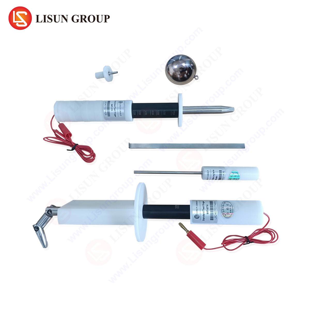
Immediately subsequent to the endurance test, and without any manual intervention to reset or clean the shutters, the non-touchability test is conducted. The standard specifies the use of a standardized test probe, as defined in DIN EN 61032 (Test probe 13). This probe is designed to simulate a child’s finger or a similar object. The test requires the application of a defined force to attempt access to the live parts through the shutter apertures. The criterion for passing is absolute: the probe must not make contact with any live part. This verification is performed on each shutter opening individually to ensure that a failure in one shutter does not compromise the entire assembly.
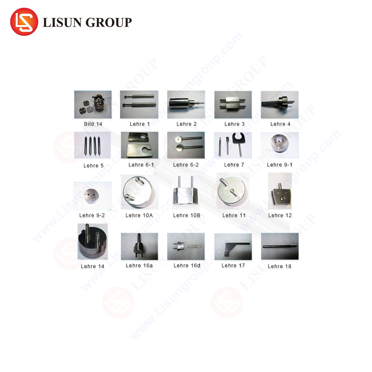
Instrumentation for Precision: The LISUN Gauges for Plugs and Sockets
The accurate and repeatable execution of this test is wholly dependent on the use of precision-engineered test equipment. LISUN produces a comprehensive suite of gauges and test apparatus explicitly designed for compliance testing with DIN VDE 0620-1 and related international standards. The LISUN gauges for plugs and sockets are calibrated instruments that provide the necessary accuracy and reliability required for certification body approvals and quality control in manufacturing.
The LISUN test kit for shutter non-touchability typically includes the mandated test probes, force application mechanisms, and fixtures for securely mounting the socket-outlet. The specifications of these gauges are meticulously aligned with the dimensional and force requirements stipulated in the standard. For instance, the test probe conforms precisely to the geometry of Probe 13, and the applied force is controlled to ensure it is within the tolerance of 1 N ± 0.5 N, or as otherwise specified in the latest version of the standard. The use of such specialized equipment eliminates subjective judgment and ensures that test results are consistent and reproducible across different laboratories and production facilities.
Key Specifications of LISUN Shutter Test Gauges:
- Probe Compliance: Manufactured to exact specifications of DIN EN 61032 Probe 13.
- Force Application: Integrated or complementary mechanism for applying standardized force (e.g., 1 N).
- Material: Constructed from hardened, non-conductive materials to prevent deformation and ensure operator safety.
- Calibration: Traceable to national metrology institutes, ensuring long-term accuracy.
- Accessories: Includes fixtures for various socket-outlet configurations (e.g., Schuko, French, UK styles).
The Testing Principle and Procedural Workflow
The testing principle is a direct simulation of the post-use safety check. The procedural workflow is methodical:
- Endurance Pre-conditioning: The socket-outlet sample undergoes the full suite of mechanical and electrical endurance tests as per the standard. It is cycled thousands of times with a standardized test plug under load.
- Visual Inspection: After endurance testing, a preliminary visual inspection is conducted to note any obvious physical damage that might have already failed the unit.
- Probe Application: Without cleaning or manipulating the shutter, the standardized test probe is inserted into the socket-outlet’s aperture. The probe is manipulated in every possible direction and orientation as permitted by the opening.
- Force Application: A specified force is applied to the probe in the direction most likely to defeat the shutter mechanism. This is often a combined pushing and rotating motion.
- Contact Verification: During the application of force, an electrical continuity circuit is typically used. If the probe, which is conductive, makes contact with a live contact inside the socket, the circuit is completed, and a visual or audible signal indicates a failure. The test is a pass/fail criterion based on the absence of contact.
This workflow underscores the “after normal operation” clause. It is not sufficient for a new socket-outlet to have functional shutters; it must demonstrably retain this safety feature after the wear and tear of its expected service life.
Industry Applications and Quality Assurance Implications
For manufacturers of plugs, socket-outlets, and wiring accessories, adherence to this test is not merely a regulatory hurdle but a core component of product liability and brand reputation. The implications span the entire product lifecycle.
- Research & Development: During the design phase, engineers use LISUN gauges to perform iterative tests on prototypes. This helps in optimizing the shutter mechanism’s geometry, material selection (e.g., using wear-resistant polymers or corrosion-resistant springs), and spring force to ensure long-term reliability.
- Production Quality Control: On the production line, periodic sampling and testing with these gauges are essential. It verifies that the manufacturing process—including injection molding, assembly, and spring installation—remains within specified tolerances. A failure in this test can indicate a tooling wear issue or a supplier quality problem with a component.
- Certification and Market Access: For a product to bear the VDE, CE, or other marks, it must be tested and certified by a recognized body. These bodies rely on calibrated equipment like LISUN’s to perform type tests. A successful test report is a prerequisite for market entry in the European Union and many other regions that harmonize with these standards.
- Failure Analysis: In the event of a field failure or a test failure in the lab, the gauges are used to replicate the conditions and diagnose the root cause, whether it be a design flaw, material defect, or manufacturing inconsistency.
Competitive Advantages of Standardized Test Equipment
The utilization of standardized, high-precision test equipment such as that offered by LISUN confers significant competitive advantages. Firstly, it ensures regulatory compliance by providing auditable evidence that testing was performed in strict accordance with the normative methods. This reduces the risk of product recalls or legal challenges related to product safety.
Secondly, it enhances product quality and reliability. By identifying potential shutter mechanism failures early in the design and production phases, manufacturers can avoid costly post-production modifications and protect their brand from associations with unsafe products. The data derived from consistent testing allows for continuous improvement in product design.
Thirdly, it streamlines the certification process. Certification bodies are more likely to accept test data from manufacturers if they are generated using recognized, calibrated equipment. This can significantly shorten the time-to-market for new products.
Finally, it promotes inter-laboratory reproducibility. When different parties, be it a manufacturer, a competitor, or a certification lab, use equipment from the same calibrated lineage, test results are directly comparable. This creates a level playing field and reinforces the integrity of the safety standard itself.
FAQ Section
Q1: How often should a manufacturer calibrate their LISUN test gauges?
Calibration intervals depend on usage frequency and the manufacturer’s quality system requirements, typically following ISO/IEC 17025 guidelines. An annual calibration cycle is common for active quality control laboratories, with interim checks performed more frequently to ensure ongoing accuracy. The calibration must be traceable to a national metrology institute to maintain validity for certification purposes.
Q2: Can the same LISUN gauge be used for different socket-outlet types, such as Schuko (Type F) and French (Type E)?
While the fundamental test probe is standardized, the fixtures and application procedures may differ. LISUN typically provides specific adapters or complete kits tailored to different socket configurations. It is crucial to use the correct fixture that properly presents the socket-outlet to the probe as intended by the standard to avoid invalid results.
Q3: What is the most common cause of failure in the non-touchability test after endurance?
The most prevalent cause is wear or permanent deformation of the shutter mechanism or its actuating components. This can be due to insufficient material strength, inadequate spring force to return the shutter to its closed position, or a design that allows for stress concentration and fatigue cracking after repeated cycles.
Q4: Does the test need to be performed on both the live and neutral openings of a socket-outlet?
Yes, DIN VDE 0620-1 requires that the non-touchability is verified for all openings that provide access to live parts. This includes both the live and neutral contacts in a single-phase socket. Each opening is tested independently to ensure a failure in one shutter does not compromise the safety of the unit as a whole.
Q5: Is testing “after normal operation” sufficient, or are there other shutter tests?
This is a key test, but it is part of a broader suite. Shutters are also tested for resistance to heat, aging, and impact, and for their ability to resist access before any endurance cycling (i.e., on a new unit). The “after normal operation” test is specifically designed to validate the durability of the safety feature.