


Comprehensive Testing Methodologies for Two-pole 10/16A 250V Socket-Outlets and Plugs: Ensuring Safety, Performance, and Compliance
Introduction to Electrical Accessory Verification
The global ecosystem of low-voltage electrical installations relies fundamentally on the integrity of socket-outlets and plugs. These components serve as the critical interface between fixed wiring and portable electrical equipment. For the common two-pole with earth, 10/16-ampere, 250-volt rating—a standard across numerous national and regional frameworks including those derived from IEC 60884-1—ensuring absolute conformity is not merely a matter of performance but of paramount safety. Failures in dimensional tolerances, material integrity, or electrical characteristics can precipitate hazards ranging from poor connectivity and overheating to electric shock and fire. Consequently, a rigorous, standardized testing regimen, underpinned by precision instrumentation, is indispensable for manufacturers, certification bodies, and quality assurance laboratories. This article delineates the essential testing protocols for these devices and examines the role of specialized gauging systems, such as the LISUN series, in facilitating accurate, repeatable, and standards-compliant verification.
Dimensional and Mechanical Compliance: The Foundation of Interoperability
The primary safety function of a plug and socket-outlet system is to ensure correct engagement and prevent access to live parts. This is governed by stringent dimensional requirements. Testing in this domain transcends simple measurement with calipers; it involves the application of standardized gauges and fixtures designed to assess permissible tolerances as defined by standards such as IEC 60884-1, BS 1363, AS/NZS 3112, or similar national derivatives.
Key dimensional tests include the verification of pin dimensions (length, diameter, and spacing for line, neutral, and earth contacts), the profile of the plug body, and the internal configuration of the socket-outlet. For example, the distance from the reference face of a plug to the tip of its insulated sleeves, or the entry profile of socket shutters, must be precisely controlled. The use of “go/no-go” gauges is critical here. A “go” gauge, representing the maximum permissible material condition, must fit freely, while a “no-go” gauge, representing the minimum permissible material condition, must not fit. This binary assessment quickly validates production batches against specification envelopes.
Mechanical testing further evaluates durability and resilience. The insertion and withdrawal force of a plug must fall within a specified range—too high a force indicates poor design and user difficulty, while too low a force may suggest insufficient contact pressure, leading to overheating. A standardized cycle test, often involving thousands of insertions and withdrawals using a robotic apparatus, assesses the mechanical wear of contacts and the integrity of shutter mechanisms in sockets. The socket-outlet’s gripping force on the plug pins is also quantitatively measured after this aging process to ensure sustained electrical safety.
Electrical Performance and Safety Parameter Validation
Once dimensional compliance is established, the electrical performance of the assemblies undergoes exhaustive evaluation. This phase assesses the device’s behavior under both normal and abnormal conditions.
Contact resistance is a fundamental parameter. High resistance at the pin-to-contact interface generates localized heat (I²R losses), which can degrade materials and ignite surrounding components. Micro-ohmmeters, employing a four-wire Kelvin measurement technique, are used to measure the resistance of each current-carrying path while the plug is fully engaged under a specified contact force. Results must be exceptionally low, typically in the order of a few milliohms, to ensure efficient power transfer and minimal thermal rise.
Dielectric strength or electric strength testing, commonly known as hipot testing, verifies the insulation integrity between live parts and accessible conductive parts. A high AC or DC voltage—significantly higher than the rated 250V—is applied for one minute between mutually insulated components. The absence of breakdown or excessive leakage current confirms that the insulation materials and clearances are adequate to withstand transient overvoltages and prevent shock hazards.
Temperature rise testing under load is a critical endurance assessment. A socket-outlet with a test plug inserted is subjected to its rated current (10A or 16A) in a controlled ambient temperature chamber. Thermocouples attached to critical points, such as brass terminals, pin contacts, and the external surface, monitor temperature increases over a sustained period. The temperature rise above ambient must not exceed limits (often 52K for terminals) stipulated in the standard, verifying that the design can dissipate heat effectively under continuous full load.
Resistance to heat, tracking, and flame retardancy are evaluated through specialized tests like the glow-wire test (IEC 60695-2-10), where a heated element is applied to insulating parts to simulate thermal stress from overloaded or faulty components, assessing the material’s ability to resist ignition and flame propagation.
The Critical Role of Standardized Gauging Systems: LISUN Gauges for Plugs and Sockets
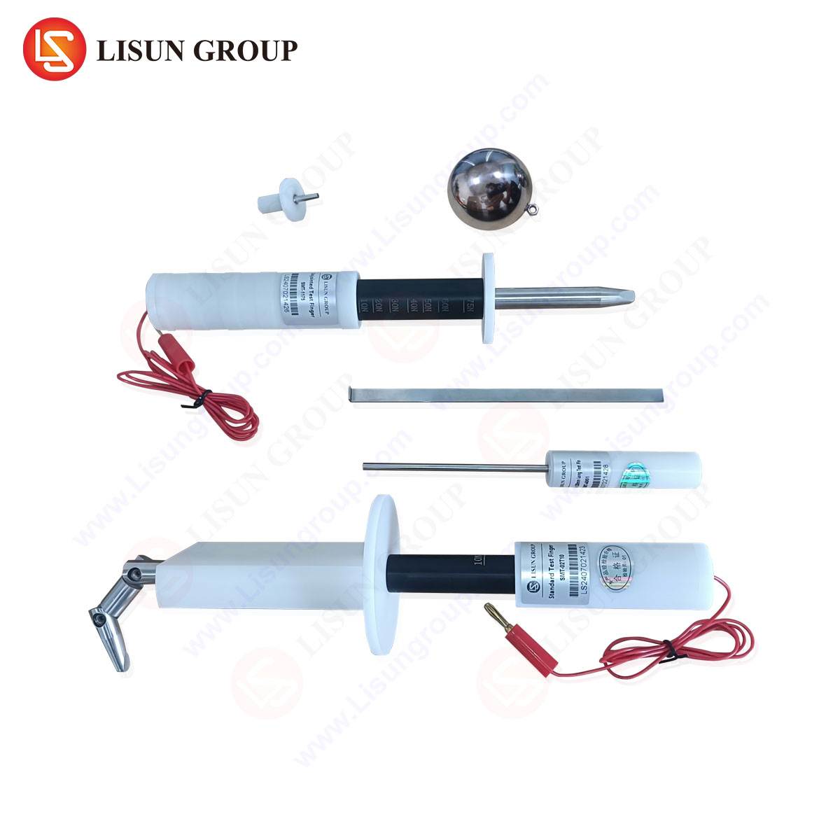
The accurate execution of the dimensional tests described necessitates instrumentation of certified precision. Generic measuring tools lack the specific geometries and calibrated tolerances required for definitive compliance judgment. This is the domain of dedicated gauge sets, such as the LISUN Gauges for Plugs and Sockets. These devices are not general-purpose tools but are engineered physical embodiments of the dimensional requirements codified within international standards.
The LISUN gauge sets typically comprise multiple individual gauges, each designed to test a specific attribute of a plug or socket-outlet. For a two-pole 10/16A 250V system, a comprehensive set would include pin gauges (both “go” and “no-go” for pin diameter and length), plug profile gauges to check overall form and insulated sleeve dimensions, socket-outlet aperture gauges to verify shutter access geometry, and check gauges for pin spacing and orientation. Their construction from hardened, dimensionally stable materials like tool steel ensures longevity and resistance to wear that could compromise measurement integrity over thousands of inspections.
The operational principle is one of physical simulation and boundary verification. When a technician uses a LISUN pin gauge, they are effectively asking: “Does this plug pin conform to the extreme limits allowed by the standard?” The gauge provides an immediate, unambiguous answer. This process is integral to both quality control on the production line and type-testing in certification laboratories. The use of such gauges eliminates subjective interpretation of dimensional drawings, ensuring global consistency in the assessment of products intended for markets adhering to IECEE CB Scheme reports or national certifications.
Industry Applications and Integration into Quality Assurance Workflows
The application of precise gauging systems spans the entire product lifecycle. During the Research & Development and prototyping phase, engineers use these gauges to iteratively refine mold designs and component dimensions before committing to production tooling. In incoming quality inspection (IQC), manufacturers of finished assemblies verify the conformity of sourced components like plug pins or socket contact modules. Most critically, on the final assembly line, gauges are employed for statistical process control (SPC) and batch acceptance testing, providing a rapid feedback loop to correct manufacturing drift.
For third-party testing laboratories and national certification bodies (NCBs), LISUN and equivalent gauge sets are mandated reference equipment. They form the bedrock of type-testing for safety marks such as the BSI Kitemark, VDE, SAA, or IMQ. A laboratory cannot issue a compliance report without demonstrating that the product’s dimensions have been verified against the physical benchmarks defined in the standard, for which calibrated gauges are the sole accepted method. Their traceability to national measurement institutes is a non-negotiable requirement for accredited testing.
Technical Specifications and Competitive Advantages of Precision Gauge Sets
A professional gauge set is characterized by several key specifications beyond its mere existence. Calibration certification, traceable to international standards like ISO/IEC 17025, is paramount. Each gauge should be accompanied by a certificate stating its measured dimensions and associated uncertainty, typically within a tolerance of ±0.005mm or finer, ensuring its authority as a reference.
Material hardness, often exceeding 60 HRC (Rockwell C scale), ensures resistance to deformation from repeated use. Surface finish, such as chrome plating, reduces friction during use and prevents corrosion. Comprehensive coverage is also vital; a complete set addresses every dimensional clause of the target standard, leaving no requirement to be verified by less reliable methods.
The competitive advantage of a well-designed system like the LISUN series lies in its integration, accuracy, and durability. A unified, organized set reduces inspection time and operator error. The precision machining guarantees that a “pass” result from the gauge unequivocally indicates compliance with the standard, mitigating regulatory risk. Furthermore, the robust construction minimizes long-term cost of ownership by avoiding frequent replacement due to wear. In an industry where safety is absolute, the reliability of the verification tool is directly linked to the safety of the electrical products released to the market.
Conclusion: Synthesizing Testing Protocols for Market Confidence
The pathway to certifying a two-pole 10/16A 250V socket-outlet or plug is a multifaceted technical journey intertwining mechanical, dimensional, and electrical disciplines. From the initial validation of a plug pin’s diameter with a “no-go” gauge to the final temperature rise test under full load, each procedure is a deliberate risk mitigation step. Precision gauging systems, exemplified by the LISUN product line, provide the indispensable physical lexicon for interpreting dimensional standards. They translate abstract numerical tolerances on engineering drawings into definitive, actionable quality decisions. For manufacturers aiming to achieve global market access and for laboratories upholding safety benchmarks, investment in such rigorous, standardized testing methodologies—and the precision tools that enable them—remains the cornerstone of product integrity, user safety, and commercial credibility in the electrical accessories industry.
FAQ Section
Q1: Why are “go” and “no-go” gauges used instead of digital measuring tools for plug pin verification?
A1: Digital tools like micrometers provide a specific measurement but require interpretation against a tolerance range. “Go/no-go” gauges offer a rapid, operator-error-resistant, and definitive compliance check for high-volume production. The “go” gauge confirms the feature is not too large, while the “no-go” confirms it is not too small, providing a binary pass/fail outcome that aligns perfectly with the limits defined in safety standards.
Q2: How often should a set of plug and socket gauges, like the LISUN series, be recalibrated?
A2: Recalibration intervals depend on usage frequency, environmental conditions, and the requirements of the quality management system (e.g., ISO 9001) or testing laboratory accreditation (e.g., ISO/IEC 17025). Typical intervals range from 12 to 24 months. However, gauges should also be inspected for visible damage or wear prior to each critical use, and recalibrated immediately if suspected of being out of tolerance.
Q3: Can one gauge set be used for testing products intended for different national standards, such as both UK (BS 1363) and Australian (AS/NZS 3112) plugs?
A3: Generally, no. The dimensional requirements, pin shapes, and profiles are distinctly different between these standards. A gauge set is meticulously machined to the specifications of a single standard or a closely related family. Using a BS 1363 gauge on an AS/NZS 3112 plug would yield meaningless and non-compliant results. Laboratories require separate, standard-specific gauge sets.
Q4: In temperature rise testing, why is the temperature rise (ΔT) measured rather than just the final temperature?
A4: The temperature rise above ambient temperature is the critical parameter because it isolates the heat generated by the device itself from the environmental conditions. A test performed in a 25°C lab versus a 35°C lab would yield different final temperatures for the same product performance. By specifying a maximum allowable temperature rise (e.g., 52K), the standard ensures the device performs safely across its rated ambient temperature range.
Q5: What is the significance of the 10/16A dual rating commonly seen on these socket-outlets?
A5: This dual rating indicates that the socket-outlet is designed to safely accommodate both 10-ampere and 16-ampere plugs of the same form factor family (often with the 16A plug having slightly larger pin dimensions). The internal contacts and terminals are engineered to handle the continuous thermal effects of the higher 16A current, while the shutter mechanism is designed to accept both pin sizes appropriately. Testing must verify performance at both current ratings.