


The Role of Precision Thermal Shock Testing in Modern Product Validation
The relentless drive for miniaturization, increased functional density, and global market deployment of electrical and electronic equipment has placed unprecedented demands on product reliability. Components and assemblies are subjected to thermal stresses not only during operation but throughout their lifecycle—from manufacturing and transportation to storage and end-use in diverse climatic conditions. These stresses, induced by rapid temperature fluctuations, are a primary catalyst for failure mechanisms such as solder joint cracking, delamination, coefficient of thermal expansion (CTE) mismatches, and material fatigue. Consequently, simulating and accelerating these conditions in a controlled laboratory environment is a non-negotiable phase in the product development and qualification cycle. Thermal shock testing, a specific and severe form of environmental stress screening, stands as a critical methodology for precipitating latent defects and validating product robustness.
Fundamental Principles of the Two-Zone Thermal Shock Methodology
Thermal shock testing diverges from conventional temperature cycling by its emphasis on rate of change. While temperature cycling involves controlled ramps between extremes, thermal shock enforces an abrupt, nearly instantaneous transfer of test specimens between two independently controlled temperature zones. This methodology, governed by standards such as IEC 60068-2-14 (Test N: Change of temperature) and MIL-STD-202G Method 107G, is designed to induce high mechanical stress due to rapid thermal contraction and expansion.
The underlying physics is governed by the fundamental relationship between thermal strain (ε) and the change in temperature (ΔT), expressed as ε = α * ΔT, where α is the coefficient of thermal expansion. A rapid ΔT creates significant strain differentials between dissimilar materials within an assembly. For instance, the bond between a silicon die (α ≈ 2.6 ppm/°C) and an epoxy molding compound (α ≈ 8–15 ppm/°C) experiences cyclical shear stress during repeated shocks. The two-zone (also called “basket transfer”) method is the most severe and widely accepted technique for simulating these conditions. It utilizes separate high-temperature and low-temperature chambers, between which a basket carrying the test specimens is mechanically transferred. The transfer time is a critical parameter, with standards often specifying a sub-10-second window to maximize the thermal gradient imposed on the units under test (UUTs).
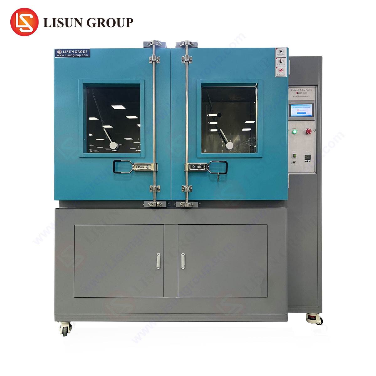
Architectural Implementation: The HLST-500D Thermal Shock Test Chamber
The efficacy of a thermal shock test is intrinsically tied to the performance and precision of the testing apparatus. The LISUN HLST-500D Thermal Shock Test Chamber embodies a refined implementation of the two-zone air-to-air methodology. Its architecture is engineered to meet the stringent requirements of modern electronic validation protocols.
The chamber is bifurcated into a high-temperature zone and a low-temperature zone, each with independent, high-precision control systems. A vertically moving basket assembly, driven by a servo-motor system, facilitates the rapid transfer of test specimens. The design prioritizes thermal stability and recovery; each zone is heavily insulated and equipped with high-capacity heating elements and refrigeration systems to minimize temperature fluctuation upon the introduction of the basket and UUTs. Key to its operation is the minimization of thermal “carry-over” and cross-talk between zones, a factor that can dilute the severity of the test.
Technical Specifications of the HLST-500D:
- Test Volume: 500 Liters (internal dimensions customizable per fixture needs).
- Temperature Range: High Temperature Zone: +60°C to +200°C; Low Temperature Zone: -10°C to -65°C (extendable to -80°C with optional cascade refrigeration).
- Temperature Recovery Time: ≤ 5 minutes (a critical metric defining test severity after basket transfer).
- Transfer Time: ≤ 10 seconds (meeting the most rigorous standard specifications).
- Temperature Fluctuation: ≤ ±0.5°C.
- Temperature Deviation: ≤ ±2.0°C.
- Control System: Digital programmable controller with multi-segment profile editing, real-time graphing, and data logging capabilities compliant with 21 CFR Part 11 for audit trails where required.
Industry-Specific Applications and Failure Mode Precipitations
The HLST-500D finds application across a broad spectrum of industries where electronic reliability is paramount. Its function is to precipitate specific failure modes relevant to each sector.
Automotive Electronics & Aerospace Components: In these domains, components must endure extreme environmental swings. An engine control unit (ECU) may experience rapid cooling from under-hood operational temperatures to cold ambient conditions. Thermal shock testing validates the integrity of ball grid array (BGA) solder joints, conformal coatings, and encapsulated sensors. Failure modes such as pad cratering or interconnect fractures are rapidly accelerated.
Telecommunications Equipment and Industrial Control Systems: Hardware deployed in outdoor cabinets or industrial settings is subject to daily and seasonal cycles. The testing of fiber optic transceivers, network switches, and programmable logic controllers (PLCs) focuses on hermetic seal integrity, connector stability, and the reliability of plated through-holes (PTHs) in printed circuit boards (PCBs).
Medical Devices and Consumer Electronics: For implantable devices or critical monitoring equipment, failure is not an option. Thermal shock screens for latent manufacturing defects in battery assemblies, micro-welds, and biocompatible material interfaces. In consumer electronics like smartphones, it tests the resilience of display laminations, solder joints for miniaturized components, and the mechanical integrity of housing adhesives after repeated “drop” from operating to standby temperatures.
Lighting Fixtures and Electrical Components: LED-based lighting systems, particularly for automotive or outdoor use, are prone to failure from thermal stress at the die-attach level and within the driver circuitry. Switches, sockets, and relay systems are tested for contact stability and insulation material cracking after rapid thermal transitions.
Comparative Advantages in Precision and Control
The value of a thermal shock chamber is measured by its ability to deliver a consistent, repeatable, and standards-compliant stressor. The HLST-500D demonstrates several competitive advantages rooted in its engineering.
First, its optimized airflow and heat exchanger design within each zone ensures exceptional temperature uniformity, often exceeding the requirements of relevant standards. This guarantees that all UUTs within the basket experience an identical thermal environment, eliminating a key variable from test results. Second, the servo-driven basket transfer mechanism provides not only speed but also smooth, repeatable motion with precise positioning, reducing mechanical vibration—an unintended secondary stressor. Third, the advanced refrigeration system, often employing a dual-stage or cascade configuration for lower temperatures, ensures stable pull-down rates and recovery performance, maintaining test severity even during high-thermal-mass load conditions.
Furthermore, the integration of a comprehensive data acquisition system is paramount. The ability to document not just the chamber air temperature, but also to monitor and log product temperature via independent sensors (e.g., thermocouples attached to critical UUT locations) provides invaluable insight into the actual thermal experience of the product. This data is crucial for correlating test conditions with field failure rates and for refining test profiles.
Integration into Broader Reliability Testing Regimens
Thermal shock testing is rarely performed in isolation. It is a core component of a Highly Accelerated Life Test (HALT) or Environmental Stress Screening (ESS) regimen. Typically, products may first undergo HALT to discover design limits, followed by a defined thermal shock profile as part of a qualification test plan derived from standards like AEC-Q100 for automotive ICs or Telcordia GR-63 for telecom equipment. The defects precipitated by the HLST-500D are then analyzed through techniques such as scanning acoustic microscopy (CSAM), X-ray inspection, or electrical testing, providing direct feedback to design and manufacturing processes.
The selection of test parameters—temperature extremes, dwell times, number of cycles—is a critical engineering decision based on the product’s intended use environment, its material construction, and the specific failure mechanisms targeted. A typical profile for automotive electronics might involve 1,000 cycles between -40°C and +125°C, with 15-minute dwells, while a commercial electronic device might be tested over 200 cycles between 0°C and +70°C.
Conclusion
As product lifecycles compress and reliability expectations escalate, the role of predictive, accelerated testing becomes more central. The thermal shock test, executed with precision by equipment such as the HLST-500D chamber, serves as a vital gatekeeper. It provides a quantifiable, repeatable means of assessing a product’s resilience to one of the most fundamental physical stresses it will encounter. By deliberately inducing failures in the laboratory, manufacturers across the electrical, electronic, automotive, and aerospace industries can implement corrective actions, thereby enhancing product durability, reducing warranty costs, and ultimately ensuring functional integrity in the field. The data generated transcends simple pass/fail metrics; it feeds into finite element analysis (FEA) models, informs material selection, and solidifies the correlation between accelerated laboratory testing and real-world service life.
Frequently Asked Questions (FAQ)
Q1: What is the primary difference between thermal shock testing and temperature cycling, and when should each be used?
A1: The core distinction lies in the rate of temperature change. Thermal shock testing utilizes a near-instantaneous transfer between two extreme temperature zones to induce high mechanical stress, ideal for identifying latent manufacturing defects and interconnect failures. Temperature cycling employs controlled ramp rates between extremes, better simulating real-world operational cycles and provoking fatigue-related failures over more cycles. Thermal shock is often used for qualification and screening, while temperature cycling is common for lifetime prediction and reliability growth testing.
Q2: How is the appropriate temperature range and number of cycles determined for a thermal shock test profile?
A2: Profile development is based on several factors: the product’s specified operational and storage environments (derived from standards like IEC 60721), the materials used (particularly their glass transition temperatures and CTEs), and the targeted failure mechanisms. Common industry standards (e.g., JEDEC, IPC, MIL) provide baseline profiles. The final profile is often a tailored combination of standard requirements and historical field failure data, intended to achieve the desired reliability goal without over-testing.
Q3: For the HLST-500D, what impact does the thermal mass of the product load have on test performance, and how is this mitigated?
A3: High product thermal mass can extend temperature recovery time after basket transfer, potentially reducing the test’s severity if the dwell time is insufficient. The HLST-500D mitigates this through its high-capacity heating and refrigeration systems designed for rapid recovery (≤5 minutes). Proper test planning is also essential: fixtures should be designed to maximize airflow around UUTs, and dwell times must be validated to ensure the product’s internal temperature stabilizes at the setpoint before the next transfer.
Q4: Can thermal shock testing be performed on powered, functioning units?
A4: Yes, in-circuit thermal shock testing is a more advanced and valuable methodology. It allows for real-time functional monitoring during the stress cycles, enabling the detection of intermittent failures that may only occur at temperature extremes. The HLST-500D can be configured with electrical feed-through ports to facilitate in-circuit testing, though special attention must be paid to cable management and the potential for heat conduction along wires.
Q5: How does data logging and compliance with standards like 21 CFR Part 11 benefit the testing process?
A5: Comprehensive, tamper-proof data logging is critical for auditability and technical analysis. It provides irrefutable evidence that the qualification test was performed as specified. Compliance with 21 CFR Part 11 (relevant for medical device validation) ensures electronic records and signatures are trustworthy and reliable. This data is used not only for certification but also for root-cause analysis when failures occur, allowing engineers to correlate specific test conditions with failure events.