


The Role of Thermal Shock Testing in Product Qualification and Reliability Engineering
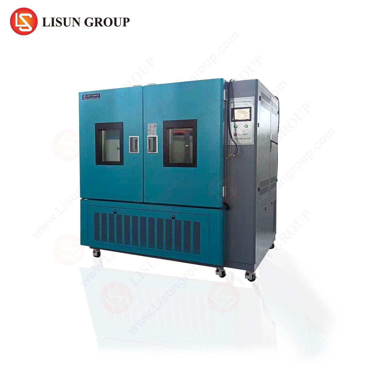
Product reliability is a non-negotiable requirement across a spectrum of industries, from automotive electronics to medical devices. The ability of a component or assembly to withstand sudden, extreme temperature transitions is a critical indicator of its structural integrity, material compatibility, and long-term performance. Thermal shock testing, a specialized form of environmental stress screening, is engineered to uncover latent defects and weaknesses that other testing methods may miss. This procedure subjects test specimens to rapid transfers between extreme hot and cold environments, accelerating the effects of thermal expansion and contraction. The resulting mechanical stresses can reveal failures in solder joints, delamination of materials, cracking of components, and other flaws induced by coefficient of thermal expansion (CTE) mismatches. The HLST-500D thermal shock test chamber is an instrument designed to execute these tests with precision, repeatability, and compliance with international standards.
Fundamental Principles of Thermal Shock Stress
The underlying physics of thermal shock testing is governed by the fundamental principle of thermal expansion. When a material is heated, its molecular structure gains kinetic energy, causing it to expand. Conversely, cooling causes contraction. Different materials within an assembly, such as ceramic integrated circuit packages, copper lead frames, and FR-4 printed circuit board substrates, possess distinct coefficients of thermal expansion. During a rapid temperature change, these materials expand and contract at different rates, generating shear and tensile stresses at their interfaces. These cyclical stresses are the primary drivers of failure mechanisms like fatigue cracking, solder joint rupture, and wire bond breakage. The objective of thermal shock testing is not to simulate a real-world environment where such rapid shifts occur daily, but to apply an exaggerated, accelerated stress to force these failure mechanisms to manifest in a condensed timeframe, thereby providing a predictive measure of field reliability and product lifespan.
Apparatus and Operational Specifications of the HLST-500D Chamber
The HLST-500D is a three-zone thermal shock test chamber, comprising a high-temperature zone, a low-temperature zone, and a transition basket that shuttles the test specimens between them. This design ensures extreme temperature stability within each zone and minimizes transfer time, which is critical for applying the intended severe thermal stress.
Key Specifications:
- Temperature Range: High Temperature Zone: +60°C to +200°C; Low Temperature Zone: -10°C to -65°C
- Recovery Time: ≤ 5 minutes (from +150°C to -55°C after loading)
- Transition Time: ≤ 15 seconds (mechanical transfer between zones)
- Temperature Fluctuation: ±0.5°C
- Temperature Deviation: ±2.0°C
- Basket Capacity: Standard loading configuration
- Internal Dimensions: 500mm x 500mm x 400mm (W x D x H)
- Control System: Digital programmable controller with real-time data logging and USB interface
- Safety Features: Over-temperature protection, phase loss protection, compressor over-pressure protection, and dry-heat protection
The chamber’s operation is predicated on precise mechanical movement. The test specimens are loaded onto a basket located in the ambient or pre-conditioned standby area. Upon initiation of a test cycle, the basket automatically transfers into the high-temperature zone and dwells for a user-defined period. After the dwell time elapses, the basket rapidly moves into the low-temperature zone for an equivalent dwell period. This cycle repeats for the specified number of times. The speed of the transfer is a critical parameter, as a prolonged transition allows the specimens to stabilize at an intermediate temperature, mitigating the intended shock effect.
Developing a Formalized Thermal Shock Test Protocol
A rigorous test procedure is essential for generating valid, reproducible, and defensible data. The following protocol outlines the steps for conducting a test using the HLST-500D, adhering to common standards such as IEC 60068-2-14 and MIL-STD-883.
Phase 1: Pre-Test Preparation and Planning
- Test Standard Selection: Define the governing test standard based on the product’s end-use industry (e.g., JESD22-A106 for semiconductors, ISO 16750-4 for automotive electronics).
- Fixturing and Mounting: Design and implement fixtures to securely hold the test specimens within the basket. The fixturing must not insulate the specimens or impede airflow, yet it must prevent damage during rapid acceleration and deceleration of the basket.
- Functional Testing: Prior to environmental stress, all specimens must undergo full functional electrical testing to establish a known-good baseline. Key parameters should be recorded.
- Chamber Setup: Program the HLST-500D controller with the specified test profile, including high temperature (TH), low temperature (TC), dwell times at each extreme, number of cycles, and transition parameters. Validate that both the high and low zones have stabilized at their target setpoints.
Phase 2: Test Execution and Monitoring
- Loading: Place the pre-tested and documented specimens into the chamber basket, ensuring they are not touching each other to allow for uniform air circulation.
- Initiation: Start the test cycle. The chamber will automatically begin the sequence of transfers and dwells.
- In-Process Monitoring: For tests requiring in-situ monitoring, ports are available for connecting electrical feed-throughs. This allows for continuous or intermittent functional testing of specimens during the stress cycles, which is invaluable for identifying the exact cycle at which an intermittent or catastrophic failure occurs.
- Data Logging: The chamber’s data acquisition system should be set to record the temperature profiles of both zones and the basket movement timestamps throughout the test duration. This provides an audit trail for test validity.
Phase 3: Post-Test Analysis and Reporting
- Recovery: Upon test completion, allow the specimens to stabilize at standard ambient conditions (e.g., 25°C, 50% RH) for a sufficient period to dissipate any residual moisture condensation.
- Final Functional Testing: Perform the same battery of electrical and functional tests conducted during the pre-test phase. Compare results to identify parametric shifts or complete failures.
- Visual and Mechanical Inspection: Conduct a microscopic examination of specimens for physical defects: cracked components, broken leads, solder joint fractures, delamination of PCBs, or deformations.
- Failure Analysis: For any failed units, perform root cause analysis (RCA) to determine the exact failure mechanism (e.g., solder fatigue, chip cracking). This data is fed back into the design and manufacturing process for corrective action.
- Report Generation: Compile a comprehensive test report including the test standard, chamber model (HLST-500D), full test profile, pre- and post-test data, photographs of failures, and conclusions regarding the product’s compliance with its reliability requirements.
Industry-Specific Applications and Use Cases
The HLST-500D is deployed across industries to qualify components and systems for reliability.
- Automotive Electronics: Electronic control units (ECUs), sensors, and infotainment systems are tested to standards like ISO 16750-4. A typical profile might cycle between +125°C (simulating engine bay heat) and -40°C (simulating cold startup) to validate solder integrity and component performance.
- Aerospace and Aviation Components: Avionics systems must operate after exposure to extreme high-altitude cold and rapid heating. Testing often involves transitions from -65°C to +125°C to ensure functionality after drastic pressure and temperature changes.
- Telecommunications Equipment: Base station electronics, fiber optic transceivers, and network switches undergo thermal shock to guarantee uptime despite daily temperature swings in outdoor enclosures.
- Medical Devices: Implantable devices and surgical tools are subjected to stringent shock tests to ensure no material degradation or failure occurs during sterilization processes (e.g., autoclave heating) or storage.
- Lighting Fixtures: LED components and drivers are tested for resilience against thermal cycling, which can cause phosphor degradation, solder joint failure, and lens cracking, ultimately impacting lumen output and lifespan.
Comparative Advantages of the Three-Zone Testing Methodology
The HLST-500D’s three-zone design offers distinct advantages over two-zone or liquid bath methods. The dedicated standby zone allows for pre-conditioning of the basket and minimizes thermal inertia, contributing to the rapid sub-15-second transfer time. This is significantly faster than many single-compartment air-to-air chambers that must purge and then heat/cool the entire workspace. Furthermore, it avoids the potential contamination and cleaning complications associated with liquid-based thermal shock tests. The independent control of the hot and cold zones ensures unparalleled temperature stability and recovery, meaning the chamber is ready for the next transfer almost immediately after the basket leaves a zone. This leads to higher throughput and more consistent application of stress across all test cycles.
Interpreting Test Data and Failure Mode Analysis
The outcome of a thermal shock test is not merely a pass/fail status. The data provides critical insights into the product’s design and manufacturing maturity. A high rate of early-life failures (e.g., within the first 10 cycles) typically indicates gross manufacturing defects, such as poor solderability or handling damage. Failures that occur consistently in the middle of the test regimen are often indicative of a design flaw, such as an inherent CTE mismatch that was not properly accounted for. Failures that only appear in later cycles are usually related to material fatigue and provide valuable data for modeling the product’s useful life. Correlating the electrical failure data with physical analysis allows engineers to make targeted improvements.
Frequently Asked Questions (FAQ)
Q1: What is the critical difference between thermal shock testing and temperature cycling?
A1: The primary distinction is the rate of temperature change. Thermal shock testing emphasizes an extremely rapid transition between extreme temperatures (often in seconds) to induce high mechanical stress. Temperature cycling involves slower, more gradual ramps between setpoints (often in minutes or hours) and is typically used to simulate more realistic environmental conditions over time.
Q2: How do we determine the appropriate dwell time for our product during a test cycle?
A2: Dwell time is typically specified by the relevant industry test standard. The principle is to ensure the entire test specimen, including its core or most massive component, reaches thermal equilibrium with the chamber environment. For most electronic assemblies, a dwell time of 30 minutes to one hour is common. Computational modeling or internal temperature probes can be used to verify soak-out.
Q3: Can the HLST-500D accommodate in-situ (live) electrical testing during the shock cycles?
A3: Yes, the HLST-500D can be equipped with electrical feed-through ports. This allows for connecting wires from the test specimens to external monitoring equipment outside the chamber. This is essential for identifying the precise moment of failure during a cycle rather than only discovering it during post-test inspection.
Q4: Our product generates its own heat during operation. How does this factor into test setup?
A4: This is a critical consideration known as “powered” or “dynamic” testing. The chamber’s setpoints must be adjusted to account for the device’s self-heating. For example, if a device under test (DUT) raises its own temperature by 15°C, and the test requires a 100°C ambient, the chamber’s high zone should be set to 85°C. Thermal characterization of the powered DUT is necessary beforehand to establish these offsets.
Q5: What maintenance is required to ensure the long-term accuracy of the HLST-500D chamber?
A5: Regular preventive maintenance is crucial. This includes periodic cleaning of the air filters to ensure proper airflow, checking and calibrating temperature sensors (e.g., annually), inspecting mechanical components like basket motors and guides for wear, and ensuring the refrigerants and heaters are operating within specified parameters. A log of all maintenance activities should be kept.