


Fundamentals of Thermal Shock Stress Testing
Thermal shock testing is an accelerated reliability assessment designed to evaluate the robustness of materials and assemblies when subjected to extreme and rapid temperature transitions. Unlike gradual temperature cycling, thermal shock induces significant mechanical stress in a very short timeframe. This stress originates from the differential expansion and contraction rates of dissimilar materials within a component, such as the silicon die, solder joints, epoxy encapsulants, and copper leads in a microchip. When these materials are bonded, their distinct coefficients of thermal expansion (CTE) cause them to expand and contract at different rates during a temperature change. The resulting shear and tensile forces can instigate latent defects, leading to catastrophic failure. The primary objective of thermal shock testing is not to simulate real-world usage conditions, which rarely involve such instantaneous changes, but to rapidly uncover workmanship flaws, design weaknesses, and manufacturing inconsistencies that would otherwise manifest as premature field failures. It serves as a highly effective screening tool, separating robust products from those with inherent vulnerabilities.
Operational Principles of Two-Zone Thermal Shock Chambers
The two-zone thermal shock chamber is a predominant apparatus for executing this stringent test methodology. It consists of two independently controlled climatic zones: a high-temperature chamber and a low-temperature chamber. A vertically or horizontally moving basket, which holds the test specimens, shuttles rapidly between these two zones. The test cycle begins with the basket residing in one chamber, allowing the specimens to soak until thermal equilibrium is achieved. Upon completion of the soak, the basket transfers the specimens to the opposite chamber in a matter of seconds. This transfer time is a critical parameter, as a prolonged transition can allow the specimens to partially stabilize at an intermediate temperature, thereby mitigating the intended shock effect. Following the transfer, the specimens undergo a second soak period in the new chamber before the cycle repeats. The rapidity of this transition is the defining characteristic of the test, creating the steep thermal gradient necessary to generate the internal stresses that provoke failure mechanisms like solder joint cracking, die delamination, wire bond failure, and ceramic substrate fracturing.
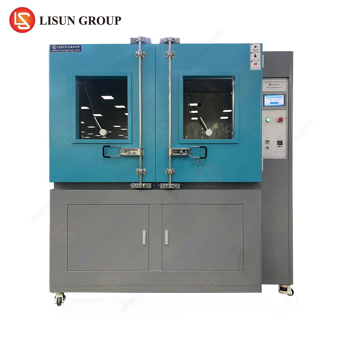
Analyzing the HLST-500D Thermal Shock Test Chamber
The LISUN HLST-500D thermal shock test chamber exemplifies the engineering precision required for reliable two-zone testing. This model is designed with an upper high-temperature zone and a lower low-temperature zone, between which a basket automatically transfers the test load. The chamber’s internal dimensions are precisely configured to provide a usable test volume of approximately 500 liters, accommodating a range of product sizes from small electronic components to larger sub-assemblies. The temperature range for the high-temperature zone typically extends from ambient +10°C to +200°C, while the low-temperature zone can achieve temperatures from ambient -10°C down to -65°C. The recovery time—the duration required for each chamber to return to its setpoint temperature after the basket transfer—is a key performance metric, and the HLST-500D is engineered for rapid recovery to maintain test integrity. The basket transfer time is specified to be less than 10 seconds, ensuring the specimens experience a near-instantaneous change in ambient conditions. Constructed from SUS#304 stainless steel and utilizing high-efficiency insulation, the chamber is built for durability and minimal thermal loss. The refrigeration system often employs a cascade compression design to reliably achieve and maintain the demanding low temperatures.
Failure Mechanisms Precipitated by Thermal Shock
The efficacy of thermal shock testing lies in its ability to activate specific, predictable failure modes. In the realm of electronics, the most common failure is fatigue cracking of solder interconnects. The CTE mismatch between a component (e.g., a Ball Grid Array package) and the printed circuit board (PCB) induces cyclic shear strain on the solder balls with each temperature transition. After a sufficient number of cycles, microcracks initiate and propagate, ultimately leading to an open circuit. Ceramic capacitors are another frequent casualty; the CTE disparity between the ceramic dielectric and the metallic terminations can cause termination separation or internal cracking, resulting in short circuits or a drift in capacitance. For products involving encapsulated or potted components, thermal shock can cause cohesive cracking within the potting compound or adhesive failure at the interface between the compound and the component casing. In automotive and aerospace applications, thermal shock can reveal weaknesses in connector systems, where different plastic polymers and metal contacts are mated, leading to contact retention issues or housing deformation. By systematically inducing these failures in a controlled environment, engineers can perform root cause analysis and implement corrective actions in the design or manufacturing process.
Industry-Specific Applications and Compliance Standards
Thermal shock testing is a mandated or highly recommended validation step across numerous high-reliability industries, each governed by specific standards.
In **Automotive Electronics**, components must endure the harsh under-hood environment. Standards such as ISO 16750-4 and various automaker-specific specifications define thermal shock profiles to validate engine control units (ECUs), sensors, and lighting systems, ensuring they withstand temperatures from the extreme heat of a running engine to the cold of a winter start.
For **Aerospace and Aviation Components**, the requirements are even more severe. Standards like RTCA DO-160 and MIL-STD-810H include thermal shock procedures to certify that avionics, navigation systems, and communication equipment remain operational after exposure to the rapid temperature changes experienced during ascent and descent.
The **Telecommunications Equipment** industry, governed by standards such as Telcordia GR-63-CORE and GR-1221-CORE, utilizes thermal shock to ensure central office switches, base station electronics, and fiber optic transceivers can survive power cycling and environmental stressors without degradation in signal integrity.
**Medical Devices**, particularly those used in vitro diagnostics or surgical suites, are tested per IEC 60601-1 to guarantee that rapid sterilization cycles or internal heat generation do not compromise device functionality or patient safety.
**Consumer Electronics** and **Electrical Components** are often tested against JESD22-A104 and IEC 60068-2-14, which provide standardized methods for evaluating the robustness of everything from smartphones and laptops to fundamental components like switches, sockets, and relays.
Critical Parameters in Test Profile Development
Designing an effective thermal shock test profile requires careful consideration of several interdependent parameters. The selection of temperature extremes is paramount; they should be representative of the maximum and minimum storage or operational temperatures the product might encounter, with an added margin for safety. The dwell time, or soak period, at each extreme must be sufficient for the entire test specimen to reach thermal equilibrium. For a dense, multi-layer PCB assembly, this can be significantly longer than for a single, small component. Insufficient dwell time means the core of the assembly does not experience the full temperature swing, rendering the test less severe. The number of cycles is determined by the product’s intended lifecycle; a consumer device may require a few dozen cycles, while a satellite component may require thousands. The transfer time between zones must be minimized, as previously discussed, to maximize the thermal gradient. Furthermore, the test profile must specify whether the device will be powered and monitored functionally during the test (in-situ monitoring) or tested only at intervals between cycles. In-situ monitoring provides real-time data on failure occurrence but adds complexity to the test setup.
Comparative Analysis with Steady-State Temperature Cycling
It is crucial to distinguish thermal shock testing from temperature cycling, as they serve different but complementary purposes. Temperature cycling, also known as steady-state cycling, involves slower transition rates, typically ranging from 1°C to 5°C per minute. This slower ramp allows the entire product to heat or cool more uniformly, minimizing the internal thermal gradients. Temperature cycling is excellent for simulating real-world environments, such as daily temperature fluctuations, and for accelerating fatigue failures that are driven by the absolute temperature range and the number of cycles. In contrast, thermal shock, with its near-instantaneous transitions, maximizes the thermal gradient. It is a “defect precipitation” test, highly effective at finding gross defects like poor solder bonds, cracks, and delaminations that are sensitive to the rate of temperature change, rather than the cumulative fatigue damage targeted by slower cycling. A comprehensive reliability validation program will often employ both tests: thermal shock to screen for manufacturing and workmanship defects early in the product lifecycle, and temperature cycling to predict the long-term wear-out failure rate.
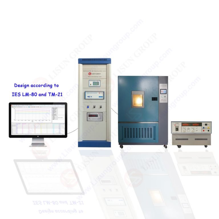
Instrumentation and Data Acquisition Methodologies
To derive meaningful data from a thermal shock test, precise instrumentation and data acquisition are non-negotiable. Thermocouples, typically Type T (copper-constantan) or Type K (chromel-alumel), are affixed to critical locations on the test specimens and, often, to the basket itself. These locations may include the surface of a high-mass component, the center of a PCB, and a point near the component leads. The data from these thermocouples is recorded throughout the test to verify that the specimens are indeed experiencing the specified temperature profile and to measure the actual thermal gradients within the product. Furthermore, the device under test (DUT) is usually connected to a monitoring system that continuously checks its electrical performance. This can involve verifying continuity, measuring resistance, monitoring signal output, or running a simplified functional test. The combination of thermal and functional data allows engineers to correlate specific temperature transitions with the onset of failure, providing invaluable insights for the failure analysis process. For a chamber like the HLST-500D, integration with a centralized data acquisition system ensures all parameters—chamber setpoints, basket position, specimen temperatures, and DUT performance—are time-synchronized and logged for comprehensive analysis.
Post-Test Analysis and Failure Mode Verification
Upon completion of the prescribed number of thermal shock cycles, a critical phase of visual inspection and electrical verification begins. All specimens undergo a thorough visual examination under magnification to identify any outward signs of distress, such as cracked casings, bulging components, or discolored substrates. Following this, the devices are tested against their full product specification to confirm operational integrity. For units that have failed during the test or during final verification, a detailed failure analysis is conducted. This process often begins with non-destructive techniques like X-ray imaging to inspect internal solder joints and C-mode Scanning Acoustic Microscopy (C-SAM) to detect delamination or voids inside encapsulated components. If a defect is located, destructive physical analysis (DPA) follows, which may involve cross-sectioning the failed area to expose the failure site for examination under a scanning electron microscope (SEM). This detailed forensic work is essential for confirming the root cause—whether it was a material defect, a design flaw, or a process-induced weakness—and for implementing effective corrective and preventive actions.
Strategic Integration in Product Development and Qualification
The strategic deployment of thermal shock testing throughout the product lifecycle is a hallmark of a mature reliability engineering process. During the design and prototyping phase, it is used as a tool for design validation, helping engineers identify and rectify fundamental weaknesses before a design is finalized. In the production validation testing (PVT) phase, it serves to qualify the manufacturing process, ensuring that the transition from prototype to mass production does not introduce new failure modes. For ongoing reliability testing (ORT), a sampling of products from the production line is periodically subjected to thermal shock to provide continuous monitoring of the manufacturing process’s health and consistency. Furthermore, the test is indispensable for supplier qualification, allowing original equipment manufacturers (OEMs) to vet the robustness of components sourced from different vendors. By integrating thermal shock testing at these critical junctures, organizations can significantly reduce the risk of field failures, lower warranty costs, and enhance their brand reputation for quality and reliability.
Frequently Asked Questions
What is the fundamental difference between the recovery time and the basket transfer time?
Recovery time refers to the duration required for the chamber air temperature to return to its designated setpoint after the basket, containing the test specimens, has been transferred into it. This is a measure of the chamber’s power and efficiency. Basket transfer time is the mere seconds it takes for the mechanical system to move the basket from one chamber to the other. A short transfer time is critical for creating the shock, while a short recovery time ensures the test profile’s severity is maintained.
How is the necessary dwell time at each temperature extreme determined?
Dwell time is not arbitrarily set; it is determined empirically. Thermocouples are attached to the slowest-to-heat/cool locations on the test specimen (e.g., the thermal mass of a product). The specimen is then subjected to the test temperatures, and data loggers record the time until all monitored points on the specimen have reached and stabilized at the target temperature. The dwell time for the formal test is then set to equal or exceed this empirically derived stabilization time.
Can thermal shock testing be performed on powered, functioning devices?
Yes, this is known as in-situ (or “powered”) testing. It requires designing a fixture that allows for electrical connections to pass from the device under test out of the chamber without impeding the basket’s movement or compromising the chamber’s seal. This method is more complex but provides superior data, as it can pinpoint the exact cycle and temperature at which a functional failure occurs.
Why is a two-zone chamber preferred over a single chamber with rapid ramping for thermal shock?
A single-zone chamber that attempts to ramp rapidly between extremes is fundamentally limited by the physics of heat transfer. The rate of temperature change is constrained by the power of the heaters and refrigeration system, and it can never achieve the near-instantaneous transition of a two-zone system where the specimen is physically moved between two pre-conditioned, stable environments. The two-zone method provides a much more severe and consistent thermal shock.