


Technical Analysis of UK Plug Testers: Principles, Standards, and Instrumentation for Electrical Safety Verification
Introduction to Electrical Safety Verification for British Standard Plugs
The integrity of a nation’s electrical infrastructure is fundamentally linked to the safety and reliability of its most basic components: plugs and sockets. In the United Kingdom, the BS 1363 standard defines the rigorous specifications for 13 A plugs, socket-outlets, adaptors, and connection units. Compliance with this standard is not merely a regulatory formality but a critical public safety imperative. Verification of this compliance necessitates specialised test equipment, commonly termed UK Plug Testers. These devices are engineered to perform a suite of electrical and mechanical assessments, ensuring that manufactured or installed components meet the exacting requirements for safe operation. This article provides a technical examination of UK Plug Tester functionality, underlying testing principles, relevant standards, and the application of advanced instrumentation, with specific reference to the LISUN Gauges for Plugs and Sockets product line.
Fundamental Testing Principles and Electrical Parameter Validation
A comprehensive UK Plug Tester operates on several core principles, each designed to interrogate a specific aspect of safety and performance. The primary electrical tests include earth continuity, insulation resistance, and polarity verification. Earth continuity testing applies a low-voltage, high-current source (typically 12V at up to 25A) between the earth pin of the plug and the protective earth contact within the socket or the appliance’s conductive parts. The measured resistance must not exceed 0.1 Ω plus the resistance of the test leads, as per BS 1363, ensuring a reliable path for fault current. Insulation resistance testing involves applying a high direct current voltage (usually 500V DC) between live parts (line and neutral, connected together) and earthed parts. A minimum resistance value of 2 MΩ is mandated, confirming the dielectric strength of the insulating materials and the absence of leakage paths that could lead to electric shock or fire.
Polarity verification, while seemingly straightforward, is vital. It confirms that the line (brown), neutral (blue), and earth (green/yellow) conductors are correctly terminated to their respective pins and socket contacts. Incorrect polarity can render switched live circuits dangerous even when off and compromise the safety of single-pole switching. Advanced testers integrate these checks into an automated sequence, providing a pass/fail indication based on pre-programmed threshold values derived from BS 1363 and the supporting guidance of the IET Wiring Regulations (BS 7671).
Mechanical Compliance: The Critical Role of Dimensional Gauging
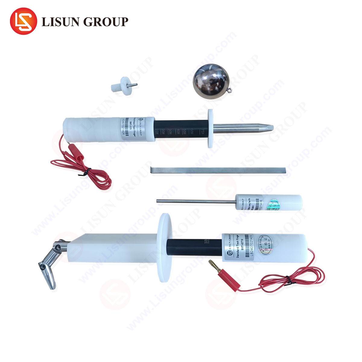
Electrical testing alone is insufficient. The mechanical geometry of a BS 1363 plug is a precisely engineered safety system. The dimensions of the insulated sleeves on the line and neutral pins, the length and profile of the earth pin, the shutter-opening mechanism within the socket, and the fuse compartment dimensions are all critical. Deviations can lead to unsafe insertion force, improper contact mating, accidental access to live parts, or the use of incorrect fuse ratings. Consequently, mechanical verification using a set of calibrated “Go/No-Go” gauges is an indispensable part of the compliance process.
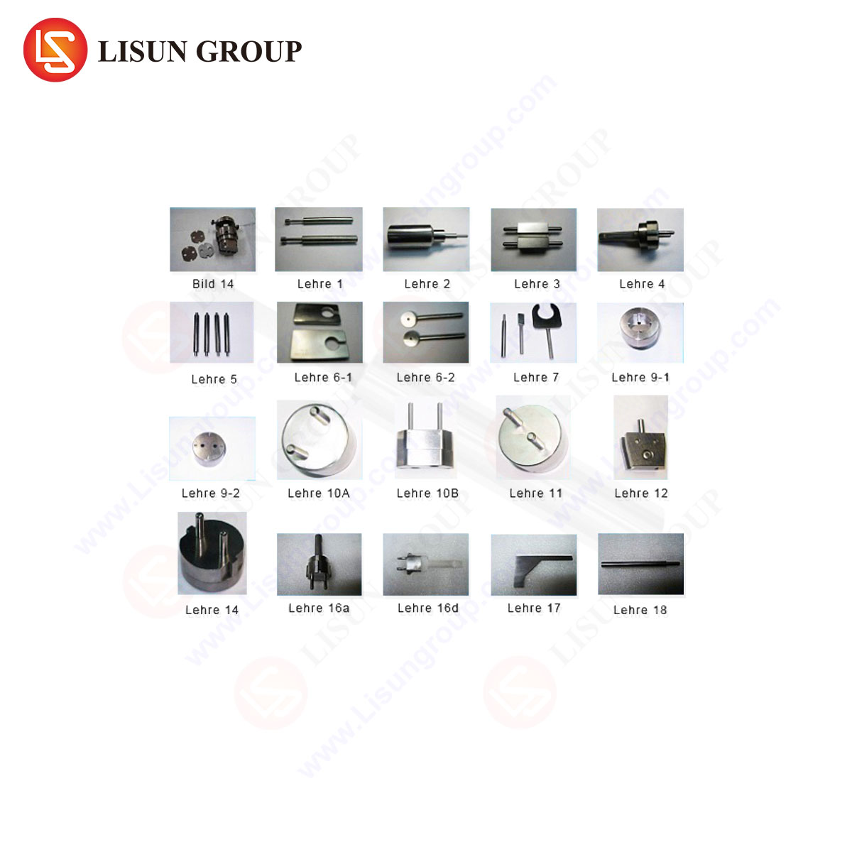
These gauges, manufactured to exacting tolerances, provide a binary assessment of dimensional conformity. For instance, a pin gauge set will include a “Go” gauge that must freely enter the pin aperture of a socket and a “No-Go” gauge that must not enter, thereby verifying the contact spacing and size is within specification. The LISUN LPS-5000 series Gauges for Plugs and Sockets exemplify this approach. This comprehensive kit typically includes gauges for:
- Pin diameter and length verification.
- Insulated sleeve length and diameter.
- Socket contact separation and shutter operation.
- Fuse dimension and compliance verification.
- Plug body dimensional checks.
Manufactured from hardened tool steel or other durable materials with certified traceability to national standards, such gauge sets provide the definitive physical reference against which production samples are judged. Their use is mandated within quality assurance laboratories of plug and socket manufacturers, certification bodies like BSI, and import/export inspection agencies.
Industry Standards Governing Test Equipment and Methodology
The performance and calibration of the test equipment itself are governed by separate standards, ensuring traceability and accuracy. Key standards include:
- BS 1363: The overarching product standard for plugs and sockets.
- BS EN 61010-1: Safety requirements for electrical equipment for measurement, control, and laboratory use.
- ISO/IEC 17025: General requirements for the competence of testing and calibration laboratories. Equipment used in accredited labs must have documented calibration histories traceable to national metrology institutes.
- BS 7671 (IET Wiring Regulations): Provides on-site installation verification requirements, influencing the design of portable testers used by electricians.
A robust UK Plug Tester system, therefore, exists within a hierarchy of standards. The device validates product compliance (BS 1363) while its own construction and accuracy must comply with safety and metrological standards (BS EN 61010-1, ISO/IEC 17025). Reference gauges, such as the LISUN LPS-5000, are themselves calibrated against master gauges held by accredited laboratories, creating an unbroken chain of measurement certainty.
The LISUN Gauges for Plugs and Sockets: Specification and Application Analysis
The LISUN LPS-5000 series represents a professional-grade solution for mechanical conformity assessment. Its design philosophy centres on durability, precision, and comprehensiveness to serve high-throughput industrial and certification environments.
Key Specifications and Components:
- Material Construction: High-carbon chromium bearing steel (or equivalent), hardened to HRC 58-62, providing exceptional wear resistance and longevity.
- Surface Finish: Precision grinding and lapping to achieve surface roughness better than Ra 0.2μm, minimising friction during gauge insertion and preventing false “No-Go” readings due to surface drag.
- Dimensional Tolerance: Gauges are manufactured to tolerances typically within ±0.005mm, significantly tighter than the product tolerances specified in BS 1363, ensuring unambiguous assessment.
- Traceability: Each gauge set is supplied with a calibration certificate from an ISO 17025 accredited laboratory, referencing UK national standards.
- Comprehensive Kit Scope: A full set addresses all critical clauses of BS 1363 related to dimensions, including but not limited to: Clause 9 (Dimensions of plugs), Clause 11 (Dimensions of socket-outlets), and Clause 13 (Requirements for adaptors).
Industry Use Cases:
- Manufacturing Quality Control (QC): Integrated into production line sampling routines. QC technicians use the gauges to perform periodic batch audits, ensuring tooling wear has not caused dimensional drift outside acceptable limits.
- Type Testing and Certification: Notified Bodies and independent test laboratories employ these gauges during initial type testing of a new product design to secure the BS 1363 mark.
- Incoming Goods Inspection: Importers, distributors, and large retailers use gauge sets to verify the compliance of sourced products before they enter the supply chain, mitigating liability risks.
- Failure Analysis and Competitor Benchmarking: Used in laboratory settings to deconstruct the physical causes of field failures or to perform comparative analysis against competitor products.
Comparative Advantages of Integrated Testing Systems
While basic pass/fail testers are available, a system integrating electrical testing with certified mechanical gauging offers distinct advantages. The LISUN approach, which often pairs electrical testers with the LPS-5000 gauge sets, provides a holistic verification platform.
Technical and Operational Advantages:
- Unified Compliance Evidence: Data from electrical tests and physical gauge checks can be consolidated into a single test report, streamlining audit and certification processes.
- Reduced Measurement Uncertainty: The use of physically calibrated gauges eliminates the potential for electronic drift or software errors in assessing mechanical dimensions, providing absolute physical verification.
- Durability in Industrial Environments: The hardened steel construction of the gauges withstands repeated use in workshop and laboratory conditions far better than purely electronic or plastic-based measurement devices.
- Alignment with Accreditation Requirements: The provision of full calibration documentation for the gauge set directly supports a laboratory’s compliance with ISO/IEC 17025, a requirement for many commercial testing contracts.
Conclusion: The Integral Role of Precision Verification in Market Safety
The ecosystem of electrical safety is built upon layers of verification. For the UK plug and socket system, a triumph of safety-oriented design, this verification is bifurcated into electrical performance and mechanical form. Advanced UK Plug Testers that encompass both domains, through integrated electrical measurement and certified physical gauging, represent the pinnacle of compliance assurance technology. Instruments such as the LISUN Gauges for Plugs and Sockets are not mere accessories but fundamental metrological references. Their application across manufacturing, certification, and import/export channels acts as a critical control point, ensuring that every component entering the market possesses the precise physical attributes required for the safe, reliable, and long-term operation of the UK’s electrical infrastructure. The continued evolution of such test equipment, in lockstep with updates to safety standards, remains a cornerstone of product safety and consumer protection.
Frequently Asked Questions (FAQ)
Q1: How frequently should a set of mechanical plug and socket gauges be recalibrated?
A1: Recalibration intervals depend on usage frequency, environmental conditions, and the quality management system requirements of the user. For laboratories accredited to ISO/IEC 17025, annual calibration is typical. High-volume production QC environments may opt for biannual checks. The manufacturer’s recommendation and the criticality of the measurements should guide the interval, which must be documented in a calibration schedule.
Q2: Can a standard digital multimeter replace a dedicated UK Plug Tester for electrical safety checks?
A2: No. A dedicated plug tester is designed to apply the specific test currents and voltages stipulated in BS 1363 under controlled conditions, with built-in safety protections. While a multimeter can measure resistance and continuity, it cannot safely apply a 25A current for earth continuity or a 500V DC potential for insulation resistance. Furthermore, it lacks the integrated sequencing and pass/fail analysis against the standard’s exact thresholds.
Q3: What is the significance of the shutter-opening mechanism test in a BS 1363 socket, and which gauge performs this?
A3: The shutters are a safety feature designed to prevent access to live contacts unless an earth pin (which is longer) is inserted first. A dedicated “shutter opening gauge” simulates the earth pin. The test verifies that the shutters open correctly with the specified force and do not open when probed with a simulated line or neutral pin alone, ensuring protection against accidental shock from object insertion.
Q4: In the context of plug testing, what is a “No-Go” gauge result indicating?
A4: A “No-Go” gauge is designed to not fit or engage if the product is within specification. For example, a “No-Go” pin gauge must not enter the pin aperture of a socket. If it does enter, this indicates the socket contact aperture is too large, representing a potential safety failure as it could accept undersized or non-compliant pins, leading to poor contact and overheating.
Q5: Does the LISUN gauge set account for all amendments to the BS 1363 standard?
A5: Reputable manufacturers like LISUN design their gauge sets to the latest published version of BS 1363, including its amendments. It is the responsibility of the end-user to specify the required standard version when procuring the equipment and to maintain awareness of standard updates. The calibration certificate supplied should reference the specific dimensional standards used for the calibration.