


A Technical Analysis of UL 1310 Figure 16.4: Compliance Strategies for Enclosure Openings
Introduction to Enclosure Integrity and Hazardous Part Accessibility
The primary function of an electrical enclosure is to provide a barrier between the user and potentially hazardous live parts, moving components, or sources of excessive temperature. Regulatory standards, such as UL 1310 for Class 2 Power Units, establish rigorous criteria to evaluate this protective integrity. Among the most critical assessments is the probe test, graphically detailed in Figure 16.4 of UL 1310. This test is not merely a dimensional check; it is a simulated evaluation of the potential for human interaction with internal hazards through openings in the enclosure. Compliance with this figure is a non-negotiable prerequisite for market access across a vast spectrum of industries, from consumer electronics to medical devices. The test seeks to answer a fundamental safety question: Can a foreign object, representing a part of the human body or a common tool, be inserted through an opening to contact hazardous parts? The methodology employs standardized test probes, each designed to simulate specific interaction scenarios, thereby ensuring a consistent and repeatable safety benchmark for manufacturers and certifying bodies globally.
Deciphering the Requirements of UL 1310 Figure 16.4
UL 1310 Figure 16.4 provides the definitive dimensional and application criteria for the test probes mandated by the standard. The figure typically delineates three primary test instruments, each with a distinct purpose:
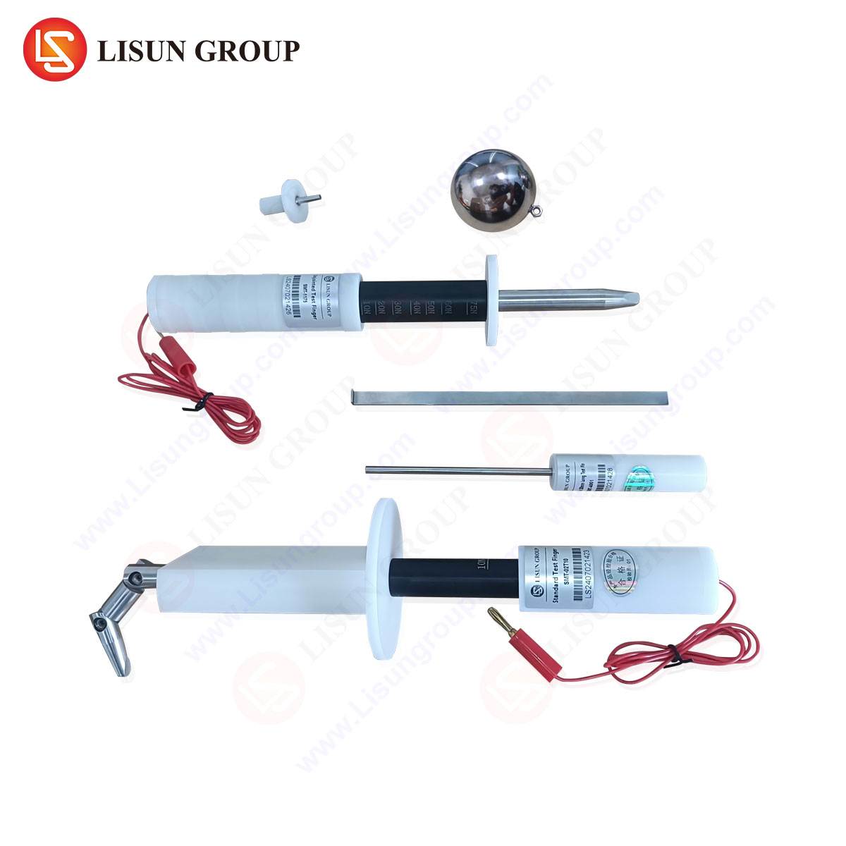
- The Jointed Test Finger: This probe simulates the dimensions and articulation of a human finger. Its purpose is to assess accessibility to hazardous live parts or dangerous moving parts (like fans or gears) through openings that a user might intentionally or accidentally probe. The test finger must not make contact with live parts or become entrapped in moving parts during its application with a specified force and articulation.
- The Test Probe (or “Pencil Probe”): A rigid, straight probe of defined diameter and length. It is intended to evaluate the accessibility through smaller openings that might be found in ventilation grilles, seams, or between components. Its design simulates the insertion of a tool, wire, or other rigid object.
- The Test Pin: A smaller-diameter, rigid probe. This instrument is used for the most restrictive openings, such as those in socket outlets, connector ports, or tiny gaps in molded casings. It represents the threat posed by small metallic objects like paperclips, pins, or component leads.
The application procedure is as critical as the probe dimensions. The standard specifies the test force (typically 30 N for the test finger, 1 N for the probe, and other values as applicable), the angle of approach, and the necessity to probe from every possible direction. The test is considered failed if any probe makes electrical contact with a live part or hazardous-energy part, or if it fails to fully release from a moving part after insertion.
The Critical Role of Standardized Test Equipment in Compliance Verification
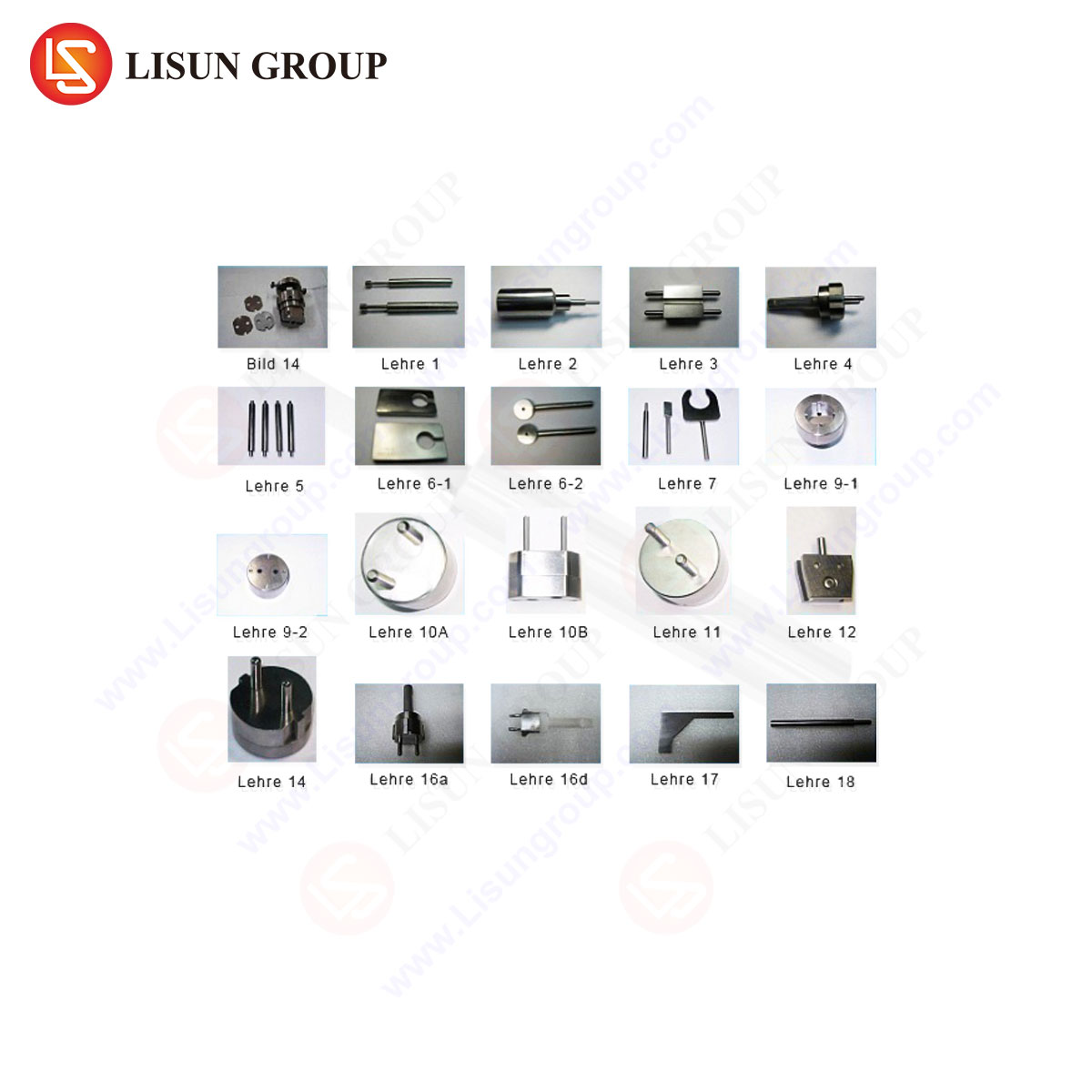
The validity of any safety standard hinges on the consistency and accuracy of the testing apparatus. Utilizing non-conforming or imprecise test probes introduces unacceptable variables, potentially leading to false passes that endanger users or false fails that incur unnecessary redesign costs. Therefore, the selection of test equipment is a foundational aspect of the compliance process. Precision-manufactured test instruments, such as those offered by LISUN, are engineered to the exacting dimensional tolerances specified in UL 1310 Figure 16.4 and its referenced standards (like IEC 61032). These tools are crafted from specified materials—often insulating materials for the test finger body and specified steel alloys for probes—to ensure correct electrical and mechanical properties. Their use guarantees that a product evaluated in a manufacturer’s internal lab will be assessed identically by a third-party Nationally Recognized Testing Laboratory (NRTL), streamlining the certification process. Beyond dimensional accuracy, high-quality test equipment features robust construction to withstand repeated use without deformation, ensuring long-term reliability of the quality assurance process.
LISUN Test Probes: Specifications and Engineering Principles
LISUN manufactures a comprehensive suite of test probes that are fully compliant with the dimensional and material requirements of UL 1310 Fig. 16.4 and related international standards. Each tool is a precision instrument designed for a specific testing modality.
LISUN Jointed Test Finger (IEC 61032 Test Probe B): This probe replicates the size and articulation of a human finger. It is constructed with articulated aluminum alloy knuckle joints to allow for natural bending, covered by an insulating material. The distal end is a hemispherical cap of precise diameter (typically 12mm). A conductive foil strip may be applied to its surface for use in “live part detection” circuits during testing. Its design allows it to be manipulated into openings from various angles with a defined force (e.g., 30 N ± 3 N), simulating a user’s exploratory action.
LISUN Test Probe (IEC 61032 Test Probe 13): Often referred to as the “pencil probe,” this is a rigid, straight rod. Its diameter is precisely machined to 2.5 mm ± 0.05 mm for the spherical end, with a total length of 100 mm. It is made of hardened steel to prevent bending during application. This probe is used to verify that openings are sufficiently small to prevent the insertion of a rigid object that could bridge hazardous potentials or interfere with internal components.
LISUN Test Pin (IEC 61032 Test Probe 18): This is the smallest standard probe, with a diameter of 1.0 mm ± 0.05 mm at its tip. It is a rigid, unbending pin of specified length, also constructed from hardened steel. Its purpose is to test the most minute openings, ensuring that even small metallic objects cannot penetrate to contact live parts. A common application is testing the shutters of socket outlets or the apertures of USB ports.
The engineering principle behind these tools is simulation through standardization. By replacing the infinite variability of real-world objects (fingers, tools, debris) with a defined set of proxies, the standard creates a reproducible and unambiguous safety threshold. LISUN’s manufacturing process ensures each probe meets these thresholds with minimal tolerance deviation, a critical factor for reliable compliance assessment.
Cross-Industry Application of Enclosure Probe Testing
The principles embodied in UL 1310 Figure 16.4 are universally applied across the electrical and electronic industries. The specific probes and their application inform critical design choices in numerous sectors.
- Household Appliances & Consumer Electronics: For devices like blenders, power adapters, and gaming consoles, the jointed test finger ensures that ventilation slots cannot be accessed by a child’s finger to contact internal wiring or a cooling fan. The test probe checks openings around button shafts or battery compartments.
- Lighting Fixtures: Recessed lighting, track lights, and LED drivers are tested to ensure that their housings prevent probe access to live terminal blocks or non-insulated LED driver outputs, even when installed in ceilings or walls where debris might fall.
- Industrial Control Systems & Automotive Electronics: Control panels, motor drives, and in-vehicle infotainment systems use these tests to ensure that service openings, cable ports, and heat sinks are designed to prevent accidental contact with high-voltage DC bus capacitors or power terminals by maintenance tools.
- Medical Devices & Telecommunications Equipment: Patient monitors, diagnostic equipment, and network routers must prevent ingress of objects into hazardous parts through ports and seams. The test pin is crucial for evaluating RJ45 jacks, fiber optic ports, and medical connector interfaces.
- Aerospace and Aviation Components: In the stringent environment of aircraft, where vibration is constant, probe testing ensures that gaps do not develop or exist that would allow a metallic object to short critical avionics lines.
- Electrical Components & Toys: Switches, sockets, and children’s products are subjected to the most rigorous probe tests. Socket shutters must resist insertion of the test pin, while toy battery compartments must be inaccessible to the test finger.
Implementing a Robust Compliance Testing Protocol
Establishing an in-house testing protocol for UL 1310 Figure 16.4 compliance is a strategic imperative for design and quality assurance teams. The protocol begins during the Computer-Aided Design (CAD) phase, where virtual clearance checks using probe models can identify potential failures early. Upon receipt of physical prototypes, a formalized test sequence should be executed.
A recommended test station includes a calibrated force gauge, a fixture to hold the unit under test (UUT), and the full set of LISUN test probes. The tester must systematically apply each relevant probe to every opening, grille, gap, and hinged or removable cover from all conceivable directions—straight on, at angles, and with articulation for the test finger. The application force must be monitored and maintained within the standard’s specified range. For electrical hazard assessment, a continuity tester (e.g., 40-50 V DC) is connected between the probe (or conductive foil on the test finger) and the live parts inside the enclosure. An audible or visual signal indicates failure. For mechanical hazards, the probe is checked for entanglement or failure to retract freely.
Documentation is paramount. The test report should detail the UUT identification, test equipment used (including serial numbers and calibration dates), each opening tested, the probe applied, the force used, and the pass/fail result. This documentation forms a critical part of the technical construction file submitted for formal certification.
Addressing Common Design Challenges and Failure Modes
Design engineers frequently encounter specific challenges when aiming to pass probe tests while meeting other product requirements like thermal management, aesthetics, and cost.
Ventilation vs. Safety: One of the most common conflicts is between the need for ample ventilation openings and the requirement to restrict probe access. The solution often lies in the geometry of the opening. A honeycomb mesh, a baffled design, or an internal shield can allow unimpeded airflow while presenting a labyrinthine path that stops the straight insertion of a probe. Computational Fluid Dynamics (CFD) and thermal testing must be used in tandem with physical probe verification.
Gaps at Seams and Interfaces: Molding tolerances, assembly fits, and hinge lines can create accessible gaps. Failure at a seam often requires a redesign of the interlocking mechanism, the addition of a tongue-and-groove feature, or the use of an internal gasket or barrier. The test is particularly stringent at points where two halves of a casing meet.
Openings for Controls and Connectors: The perimeter around buttons, knobs, and cable ports is a typical failure point. Engineers must design sufficient “depth” or “undercut” so that a probe inserted next to the shaft cannot reach a live part. For ports, internal shrouding or recessed sockets are effective solutions.
A failure during testing is not merely a setback but a valuable diagnostic tool. The specific probe that caused failure, the point of contact, and the path of insertion provide direct feedback for a targeted design iteration, moving the product closer to robust compliance.
FAQ: Common Inquiries on Probe Testing and Equipment
Q1: Can we use 3D-printed test probes for internal design verification?
While 3D-printed models can be useful for preliminary CAD clearance checks and early prototype “fit” assessments, they are unsuitable for formal compliance testing. They lack the precise material properties (hardness, rigidity, conductivity), dimensional accuracy, and durability specified in the standard. For any test that will inform a certification submission or production quality control, tools like the precision-machined LISUN probes are required to ensure results are valid and reproducible.
Q2: How often should our test probes be calibrated or replaced?
Test probes are mechanical gauges subject to wear. The jointed test finger’s joints can loosen, and the tips of rigid probes can deform or dent. It is recommended to perform a dimensional inspection against the standard’s drawing at regular intervals, such as every 6 to 12 months, or more frequently under heavy use. Any probe showing visible wear, corrosion, or dimensional deviation outside tolerance must be replaced immediately. Maintaining a calibration log for each tool is a best practice.
Q3: Our product has an IP-rated enclosure for dust and water ingress. Does this automatically ensure compliance with UL 1310 Fig. 16.4?
Not necessarily. While there is correlation, the standards serve different purposes. IP (Ingress Protection) ratings, such as IPXXB (finger-proof), are often aligned with probe tests. However, UL 1310’s assessment is specifically focused on contact with hazardous parts, not just ingress. An enclosure might be “finger-proof” (IPXXB) but could still allow a test probe to contact a live part if the internal layout is poor. Conversely, a product passing the UL probe test may not achieve a high IP liquid ingress rating. Both sets of requirements must be evaluated independently according to their respective standards.
Q4: Are the LISUN probes applicable to other standards beyond UL 1310?
Yes, absolutely. The dimensional specifications for these test probes are harmonized across many major international safety standards. The LISUN Jointed Test Finger, Test Probe, and Test Pin conform to IEC 61032, which is referenced by UL, IEC, EN, CSA, and other national standards for a vast range of products including IT equipment (IEC 60950-1 / UL 62368-1), household appliances (IEC 60335-1), and medical equipment (IEC 60601-1). A single set of LISUN probes is therefore a versatile investment for companies designing products for global markets.