


An Analysis of Contact Engagement and Withdrawal Force in Plugs and Sockets: Interpreting UL 498 Gauges Figure Typical 74.2
Introduction to Mechanical Compliance in Electrical Connectors
The operational integrity and long-term safety of plugs and sockets are contingent upon precise mechanical design as much as electrical performance. A plug that inserts with excessive force risks user strain and potential damage to the socket contact springs, while one with insufficient engagement force can lead to high-resistance connections, overheating, and ultimately, fire hazard. To objectively quantify these critical mechanical parameters, standardized test methodologies and precise gauging instruments are indispensable. Underwriters Laboratories Standard 498, “Attachment Plugs and Receptacles,” provides the definitive framework for evaluating these devices in North America. Within this standard, Figure Typical 74.2, “Gauges for Checking Engagement and Withdrawal Force of Attachment Plugs,” establishes the physical dimensional benchmarks for validating contact performance. This article provides a detailed technical examination of the principles embodied by this figure, the engineering challenges of compliance testing, and the implementation of these requirements through modern, calibrated instrumentation, with specific reference to the application of LISUN Gauges for Plugs and Sockets.
Deconstructing UL 498 Figure Typical 74.2: Dimensional Tolerances and Functional Intent
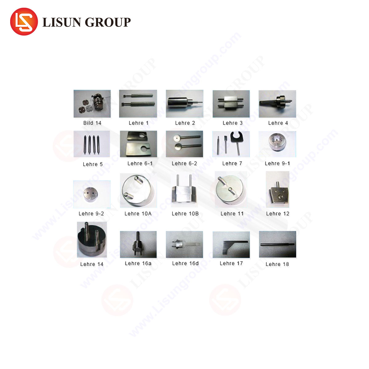
Figure Typical 74.2 is not a single gauge but a specification for a series of gauges designed to verify two distinct mechanical properties: the minimum engagement force and the maximum withdrawal force of a plug within a receptacle. The figure delineates precise dimensional drawings for “GO” and “NO GO” gauges, which simulate the plug’s contact blades (e.g., NEMA 5-15P blades) but with controlled variations in thickness and geometry.
The “GO” gauge, manufactured to the maximum permissible material dimensions as defined by the standard for the plug blades, must insert into the receptacle with a force not exceeding a specified upper limit (e.g., 30 lbf for some configurations). This test ensures the receptacle does not present undue insertion difficulty. Conversely, the “NO GO” gauge, fabricated to the minimum material dimensions allowed for the plug blades, must be retained by the receptacle contacts with a withdrawal force not less than a specified lower limit (e.g., 1.5 lbf). This verifies that even a plug at the wear limit of its specification will maintain sufficient mechanical grip to ensure electrical contact integrity. The dimensional tolerances for these gauges are exceptionally tight, often within thousandths of an inch, as they form the legal boundary between compliant and non-compliant products. Misinterpretation or use of improperly machined gauges can lead to false acceptance or rejection of products, with significant commercial and safety implications.
The Metrological Transition from Passive Gauges to Instrumented Force Analysis
Traditional implementation of Figure Typical 74.2 involves manual use of machined steel gauges with a handheld force gauge, a method prone to operator influence, inconsistent alignment, and non-linear force application. Modern quality assurance and engineering laboratories have transitioned to automated, instrumented test systems that provide objective, repeatable, and data-rich evaluations. This is where specialized apparatus like the LISUN Gauges for Plugs and Sockets system operates. Such a system transcends the basic function of the dimensional gauges by integrating them into a programmable, sensor-driven platform.
The system typically employs a precision electromechanical actuator to which the standardized gauge (machined per UL 498 Fig. 74.2) is affixed. The actuator moves the gauge into and out of the test receptacle at a controlled, constant speed, as mandated by the standard. An integrated load cell, aligned coaxially with the direction of travel, measures the force profile throughout the entire engagement and withdrawal cycle. This yields a continuous force-displacement curve rather than a single peak value. Key metrics extracted include the maximum insertion force, the average withdrawal force over a defined travel distance after full engagement, and the shape of the force curve, which can reveal issues like contact stubbing, uneven spring rates, or excessive friction.
Specifications and Operational Principles of an Integrated Gauge Testing System
A contemporary system, such as the LISUN LPSC-2 Series, embodies this integrated approach. Its specifications are designed explicitly to meet and exceed the rigors of UL 498 and analogous international standards like IEC 60884. The system features a high-resolution servo motor drive with a positioning accuracy better than ±0.01mm, ensuring repeatable gauge travel. The force measurement subsystem utilizes a calibrated strain-gauge load cell with a typical capacity of 50N (approximately 11.2 lbf) and a resolution of 0.001N, providing the sensitivity needed to accurately measure low withdrawal forces.
The operational principle is governed by programmable test sequences. The operator selects the appropriate gauge (NEMA 1-15, 5-15, 5-20, etc.), secures the receptacle fixture, and initiates the test. The system performs an automatic zeroing of the force sensor, approaches the receptacle, and executes the insertion stroke at a speed configurable to the standard’s requirement (often 25 mm/min). Upon reaching full engagement depth, it may pause for a dwell time to allow contact relaxation before initiating the withdrawal stroke. The embedded controller samples force and position data at high frequency, calculating the required pass/fail parameters in real-time. All data and curves are logged for traceability and analysis, a critical requirement for certified testing laboratories and high-volume manufacturers.
Industry Applications: From R&D Design Validation to Production Line QC
The application of such precise gauge testing spans the product lifecycle. In Research and Development, engineers use the force-displacement profiles to optimize contact spring geometry, plating materials, and housing design. For instance, analyzing the insertion curve can help identify a sharp peak force caused by the leading edge of the gauge catching on the contact entrance, prompting a redesign for smoother plug guidance. The withdrawal force profile indicates the consistency of the contact spring’s normal force across the intended blade thickness range.
In production quality control, statistical process control (SPC) relies on periodic sampling tests. Automated gauge systems allow for rapid, operator-independent testing of samples from each production batch. Trending the average withdrawal force over time can signal tooling wear in the stamping process for receptacle contacts or variations in heat treatment of spring phosphor bronze. For safety agency certification testing (UL, ETL, CSA), the use of a calibrated, automated system provides the auditable data and repeatability required to demonstrate consistent compliance with Clause 74 of UL 498.
Competitive Advantages of Automated and Data-Centric Gauge Testing
The shift from manual gauge checks to automated systems like the LISUN gauges confers several distinct advantages. First is the elimination of subjective operator error. Manual force application is rarely perfectly aligned or velocity-controlled, leading to high test result variance. Automated systems ensure identical test kinematics for every sample. Second is data integrity. The digital capture of the entire force profile provides an objective record that can be archived, reviewed, and used for deeper diagnostic analysis beyond a simple pass/fail outcome.
Third is throughput and labor efficiency. An automated system can test multiple receptacles in a fixture sequentially, calculating results automatically and generating reports without manual transcription. This increases test capacity in QC labs. Finally, flexibility is key. A robust system accommodates a library of different gauges (for various NEMA and IEC configurations) and allows for custom test programming to address internal corporate standards or investigate specific failure modes, making it a versatile tool for global manufacturers producing for multiple markets.
Interpreting Force-Displacement Curves: A Diagnostic Tool for Contact Design
The output from an instrumented gauge test is more than two numbers; it is a diagnostic signature of the receptacle’s mechanical health. A typical ideal curve shows a smooth rise to a single peak during insertion (representing the point of maximum deflection of the contact springs), followed by a slight drop as the gauge seats fully. The withdrawal curve should show a relatively flat plateau, indicating consistent spring force across the contact wipe area.
Deviations from this ideal are informative. A double peak on insertion may indicate the gauge is engaging two independent contact springs at slightly different times. An insertion curve with high-frequency oscillations suggests excessive friction or a “sticking” phenomenon. A withdrawal curve that declines sharply indicates a loss of spring normal force, potentially due to poor spring geometry or material fatigue. By correlating these curve anomalies with physical design features, engineers can perform root-cause analysis without destructive disassembly.
Integration with Broader Compliance Testing Regimes
Testing per Figure Typical 74.2 is rarely an isolated activity. It is one component of a comprehensive safety and performance test schedule. The same receptacle sample may subsequently undergo electrical overload tests, temperature rise evaluations, and durability testing (insertion/withdrawal cycles). Data from the gauge test provides a crucial baseline. For example, a receptacle showing a withdrawal force at the lower specification limit may be flagged for more stringent monitoring during temperature rise testing, as a marginal mechanical connection can lead to excessive electrical resistance and heating. Therefore, integrating gauge force data with other test station results in a centralized database provides a holistic view of product quality and predictive insights into long-term reliability.
Conclusion
UL 498 Figure Typical 74.2 encapsulates a fundamental safety premise: the electrical connection begins as a mechanical one. The evolution from passive dimensional gauges to sophisticated, instrumented test systems represents the industry’s commitment to quantifiable, repeatable, and insightful validation of this principle. Equipment such as the LISUN Gauges for Plugs and Sockets operationalizes this standard, transforming a simple go/no-go check into a rich source of engineering data. As plug and socket designs evolve for higher currents, smart functionalities, and enhanced durability, the precise measurement and analysis of contact engagement and withdrawal forces will remain a cornerstone of product safety, reliability, and performance validation. The continued refinement of these testing methodologies ensures that the humble plug-and-socket interface, a ubiquitous component of the built environment, meets its critical safety mandate through engineered precision.
FAQ Section
Q1: Why is the withdrawal force test using the “NO GO” gauge considered more critical for safety than the insertion force test?
The minimum withdrawal force test directly correlates to the integrity of the electrical connection. A plug at the minimum material condition (simulated by the “NO GO” gauge) must still be retained with sufficient force to maintain adequate contact pressure. Inadequate pressure leads to increased contact resistance, resulting in energy loss as heat at the interface. Over time, this can cause insulation degradation, contact oxidation (further increasing resistance), and potentially lead to thermal runaway and fire initiation. The insertion force test primarily addresses usability.
Q2: Can an automated gauge testing system be used for standards other than UL 498?
Yes, a flexible system is designed to accommodate multiple standards. While the gauge dimensions are specific to the blade forms defined in UL 498 (NEMA configurations), the core instrument can be programmed for other test parameters. For IEC 60884 (used in Europe and many other regions), different gauge geometries (e.g., for Europlug or Schuko pins) and different force/velocity requirements are used. A comprehensive system will offer a library of interchangeable gauge fixtures and programmable test profiles to cover UL, IEC, GB (Chinese), and other national standards.
Q3: How often should the gauges and the force sensor be calibrated?
Calibration intervals are dictated by quality system requirements (e.g., ISO/IEC 17025 for labs) and usage frequency. The physical gauges, due to their potential for wear from repeated use, should have their critical dimensions verified via coordinate measuring machine (CMM) at least annually, or more frequently in high-volume production environments. The integrated load cell of the system should undergo full-force calibration traceable to national standards (e.g., NIST) on an annual basis. Many systems also include software-based routine verification checks using certified reference weights.
Q4: What is the impact of contact plating on the force measurements?
Contact plating (typically tin, silver, or nickel) primarily affects the coefficient of friction, not the fundamental spring normal force. A higher-friction plating (like matte tin) will result in higher measured insertion and withdrawal forces compared to a lower-friction plating (like silver) on an otherwise identical contact spring. Therefore, force specifications in standards must be developed with the intended plating material in mind. An automated test system can help characterize this frictional component by analyzing the hysteresis (the area between the insertion and withdrawal curves) in the force-displacement plot.
Q5: In a production environment, is it necessary to test every single receptacle?
100% testing of engagement/withdrawal force is generally not practical or necessary. The industry standard is based on statistical sampling plans (e.g., derived from ANSI/ASQ Z1.4 or similar). A validated manufacturing process with strong process control (SPC) will use periodic sampling, such as testing a set number of units from each production batch or at defined time intervals. The frequency and sample size are risk-based, considering the product’s safety criticality and the historical stability of the production process. Automated systems facilitate this by enabling fast, reliable testing of the chosen samples.