


An Analytical Framework for UL 498 Plug Gauge Dimensional Verification
The integrity of electrical connectivity systems rests upon a foundation of precise physical dimensions. Within the North American market, the UL 498 standard, governing attachment plugs and receptacles, establishes the critical dimensional parameters that ensure safety, interoperability, and reliable performance. Compliance with this standard is not a matter of subjective assessment but requires objective, repeatable verification through calibrated plug gauges. These specialized instruments serve as the definitive arbiter of conformance, translating abstract dimensional tolerances from technical drawings into a clear pass/fail determination for manufactured components. This document provides a comprehensive examination of the dimensional requirements stipulated by UL 498 for plug blades and the corresponding gauge verification process, with a specific focus on the implementation and technical superiority of LISUN Gauges for Plugs and Sockets.
The Foundational Role of Dimensional Conformance in Electrical Safety
Dimensional inaccuracies in plug and receptacle components precipitate a cascade of potential failure modes. An undersized plug blade, for instance, fails to establish sufficient contact pressure within the receptacle contacts, leading to a high-resistance connection. This condition generates localized heat under load due to I²R heating effects, potentially degrading insulation, softening plastic housings, and in extreme cases, initiating electrical fires. Conversely, an oversized blade can cause permanent deformation of the receptacle’s spring contacts, diminishing their clamping force over time and compromising the connection for all subsequently inserted plugs. Furthermore, non-conforming blade thickness or width can prevent full insertion, leaving energized prongs exposed and creating a severe shock hazard. The pin configuration and spacing are equally critical; misalignment can lead to cross-connection, where a plug designed for a 125-volt circuit could be forcibly inserted into a 250-volt receptacle, resulting in catastrophic equipment failure. The plug gauge, therefore, functions as a primary safeguard against these risks, ensuring that every component entering the market possesses the physical geometry necessary for safe and intended operation.
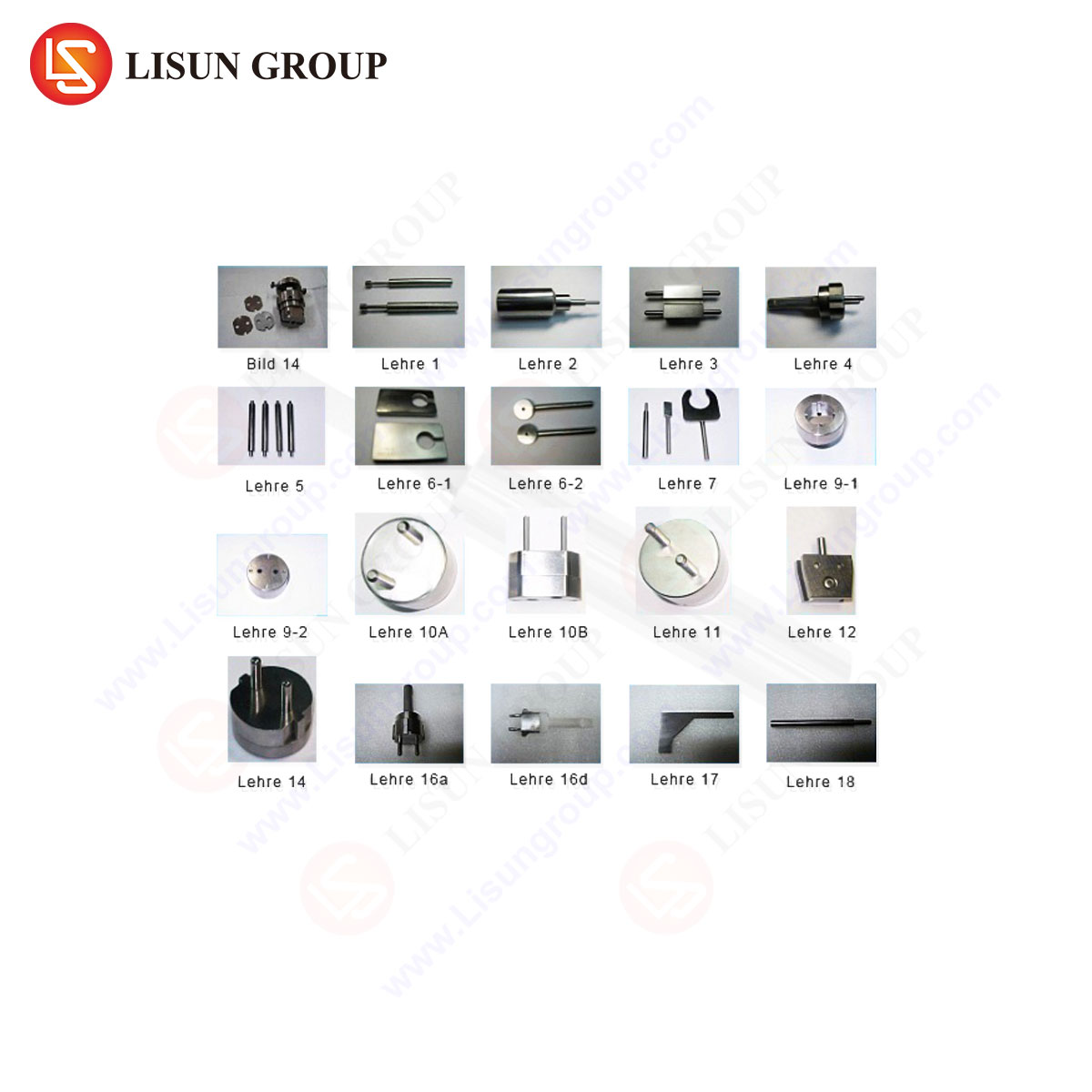
Deconstructing the UL 498 Plug Gauge Set: A Component-Level Analysis
A complete UL 498 plug gauge set is not a single tool but a collection of individual go/no-go gauges, each designed to test a specific dimensional attribute of a plug’s current-carrying blades (parallel and tandem blades) and the grounding pin. The set is meticulously engineered to assess the limits of the specified tolerances.
The “Go” Gauge Principle: This gauge represents the minimum acceptable material condition. It must freely and fully enter the corresponding receptacle slot or engage with the plug blade without binding. For a plug blade, the “Go” gauge would be a slot of the minimum allowable width and thickness that the blade must fit into. Its successful application verifies that the blade is not too large, ensuring it can be inserted into a compliant receptacle.
The “No-Go” Gauge Principle: This gauge represents the maximum acceptable material condition. It must not enter or engage under its own weight or with minimal manual pressure. For a plug blade, the “No-Go” gauge would be a slot of the maximum allowable width or thickness. Its rejection by the component verifies that the blade is not too small, ensuring it will make sufficient contact within the receptacle.
A typical set includes gauges for:
- Blade Thickness (Go and No-Go)
- Blade Width (Go and No-Go)
- Blade Length
- Grounding Pin Diameter (Go and No-Go)
- Pin Spacing (Between current-carrying blades and between a blade and the ground pin)
The application of these gauges must be performed on unenergized, clean components. The technician applies the gauge without undue force, allowing the tool’s own weight to be the primary driving force for the “Go” check. The use of excessive force invalidates the test, as it can deform either the gauge or the component under test.
Critical Dimensional Tolerances for NEMA 5-15P and 5-20P Configurations
The NEMA 5-15P (15A, 125V) and 5-20P (20A, 125V) plugs are among the most common configurations, and their dimensional requirements illustrate the precision demanded by UL 498. The following table outlines key tolerances and their functional significance.
| Dimensional Feature | NEMA 5-15P Typical Requirement | NEMA 5-20P Typical Requirement | Functional Rationale |
|---|---|---|---|
| Blade Thickness | Go: 0.060 in (1.524 mm) Min No-Go: 0.064 in (1.626 mm) Max |
Go: 0.080 in (2.032 mm) Min No-Go: 0.084 in (2.134 mm) Max |
Ensures correct contact pressure; prevents overheating or loose connections. The 20A blade is thicker to carry higher current. |
| Blade Width | Go: 0.372 in (9.449 mm) Min No-Go: 0.380 in (9.652 mm) Max |
Go: 0.372 in (9.449 mm) Min No-Go: 0.380 in (9.652 mm) Max |
Maintains alignment and prevents rotation within the receptacle. |
| Blade Length | Min: 0.688 in (17.475 mm) | Min: 0.688 in (17.475 mm) | Ensures blades engage the receptacle contacts fully before the plug face seals the outlet, preventing arcing on insertion/withdrawal. |
| Ground Pin Diameter | Go: 0.180 in (4.572 mm) Min No-Go: 0.186 in (4.724 mm) Max |
Go: 0.180 in (4.572 mm) Min No-Go: 0.186 in (4.724 mm) Max |
Ensures the grounding path is established first and broken last, a fundamental safety feature. |
| Blade Spacing | Between centers: 0.500 in ± 0.005 in (12.7 mm ± 0.127 mm) | Between centers: 0.500 in ± 0.005 in (12.7 mm ± 0.127 mm) | Guarantees interoperability with all compliant receptacles and prevents misalignment. |
It is imperative to consult the latest version of the UL 498 standard for absolute and authoritative values, as these are subject to revision. The gauges themselves must be manufactured to tolerances significantly tighter than those of the components they are testing, often an order of magnitude more precise.
LISUN Gauges for Plugs and Sockets: Engineering for Metrological Certainty
The LISUN series of plug and socket gauges are engineered to provide metrological certainty in the verification of UL 498 compliance. Constructed from high-carbon, high-chrome tool steel, these gauges undergo a multi-stage heat treatment process to achieve a surface hardness of HRC 60-63. This extreme hardness provides exceptional resistance to wear and abrasion, which is critical for maintaining dimensional integrity over thousands of testing cycles. The gauges are subsequently subjected to precision grinding and lapping operations, followed by a stabilization treatment to relieve internal stresses, ensuring long-term dimensional stability and preventing micro-deformation.
Each LISUN gauge is certified to have been manufactured with a dimensional tolerance of ±0.0005 inches (±0.0127 mm), a precision level that guarantees the accuracy of the pass/fail judgment it renders. The surfaces are finished with a black oxide coating, which not only provides corrosion resistance but also reduces friction during the testing process, preventing false “No-Go” readings caused by galling or adhesive wear. The gauges are clearly and permanently laser-etched with their function (e.g., “GO 5-15P BLADE THK”) and relevant standard references, minimizing the potential for operator error.
Competitive Advantages of the LISUN Design:
- Extended Service Life: The superior material science and hardening techniques result in a tool that maintains its critical dimensions far longer than lower-cost alternatives, reducing the total cost of ownership and calibration frequency.
- Reduced False Rejections: The optimized surface finish and precise edge breaks prevent the gauge from hanging up on minor burrs or surface imperfections that do not affect the functional dimension, leading to more accurate and repeatable test results.
- Traceable Certification: Each LISUN gauge set is supplied with a certificate of calibration traceable to NIST (National Institute of Standards and Technology), providing documented proof of compliance for quality audits and regulatory inspections.
Implementation in Quality Assurance and Production Workflows
In a manufacturing environment, LISUN plug gauges are deployed at multiple control points. At the incoming quality assurance (IQC) stage, they are used to validate shipments of molded plugs or plug assemblies from sub-suppliers. This prevents non-conforming components from entering the production line. On the factory floor, the gauges are utilized for first-article inspection (FAI) at the beginning of a production run and for periodic in-process checks, often performed at intervals defined by a statistical process control (SPC) plan.
For high-volume manufacturers, the manual application of individual gauges can be integrated into a semi-automated test fixture. A technician can place a plug into a nest, and a pneumatic or electromechanical actuator sequentially presents the “Go” and “No-Go” gauges with a consistent, pre-defined force. This method further enhances repeatability and throughput while reducing operator fatigue. The data from these tests can be logged to track tooling wear on injection molds or stamping dies, enabling predictive maintenance before the process drifts out of specification.
Correlation Between Gauge Results and Electrical Performance
The dimensional checks performed by plug gauges are directly correlated with the electrical performance tests required by UL 498. A plug that passes all gauge tests is predisposed to perform well in subsequent evaluations. For example:
- Temperature Rise Test: A plug with blades conforming to the “Go” and “No-Go” thickness and width gauges will establish optimal contact area and pressure within the receptacle. This minimizes contact resistance, which is the primary source of heat generation under load, leading to a lower and safer temperature rise during this test.
- Insertion and Withdrawal Force Test: The dimensional conformance ensures that the insertion and withdrawal forces fall within the acceptable range specified by the standard. A blade that is too thick would exceed the maximum insertion force, while a blade that is too thin would fall below the minimum withdrawal force, risking a loose connection.
- Dielectric Voltage-Withstand Test: Proper blade length, verified by gauge, ensures that the electrical connection is fully made and the plug face is seated against the receptacle wall before the circuit is energized. This prevents arcing across an air gap, which could compromise the dielectric strength of the assembly.
Therefore, dimensional verification is not an isolated activity but a proactive and predictive measure that underpins the entire safety certification process.
Frequently Asked Questions (FAQ)
Q1: How frequently should our LISUN plug gauges be recalibrated?
The calibration interval depends on usage frequency and the criticality of the application. For high-volume production environments, an annual calibration cycle is recommended. For lower-volume or reference applications, a bi-annual cycle may be sufficient. A best practice is to monitor for any drift in your statistical process control (SPC) data, which can signal the need for an unscheduled calibration check.
Q2: Can a single LISUN gauge set be used for both NEMA 5-15 and NEMA 5-20 plugs?
No. While some dimensions like blade width and spacing are shared, the critical blade thickness differs between a 15-amp and a 20-amp plug. Using an incorrect gauge will provide an invalid result. LISUN provides distinct, clearly marked gauge sets for each NEMA configuration to prevent cross-use and ensure testing accuracy.
Q3: What is the proper procedure if a plug fails the “Go” gauge check?
A failure of the “Go” gauge indicates the blade is oversized. The immediate action is to quarantine the affected production lot. The root cause must be investigated, typically focusing on the plug’s injection mold or stamping die. Common causes include tool wear, flash, or a deviation in the molding process parameters. Production should not resume until the cause is identified and corrected, and first-article inspection passes.
Q4: The “No-Go” gauge seems to fit with slight hand pressure. Is this a pass or fail?
This constitutes a failure. The “No-Go” gauge must not enter under its own weight or with minimal force. The application of “slight hand pressure” is subjective and exceeds the test conditions. A true “No-Go” condition means the gauge will not start or will stop within the first millimeter of engagement. This result indicates the blade is undersized and will not generate sufficient contact pressure in a receptacle.