


Introduction to Mechanical Safety Probes in Product Compliance
The evaluation of electrical and electronic equipment for safety hazards is a foundational element of product design and certification. Among the most critical assessments are those pertaining to accessibility of live parts and the integrity of enclosures. These tests, designed to simulate accidental contact or probing by users, children, or foreign objects, rely on a family of standardized mechanical test probes. These geometrically defined tools, often fabricated from robust materials like steel and plastic, provide a consistent and repeatable method for verifying that products meet the stringent requirements of international safety standards. Their application spans a vast range of industries, from household appliances and consumer electronics to medical devices and automotive systems, forming an indispensable part of the global safety ecosystem.
Anatomizing the
UL Test Probe: Geometry and Specifications
The
UL Test Probe, formally referenced in standards such as UL 60950-1 and its successor IEC 62368-1, is a precisely engineered device intended to verify that openings in an equipment enclosure do not permit access to hazardous live parts. Its design is not arbitrary; every dimension is calibrated to represent a specific threat model, typically the probing action of a slender object or a child’s finger.
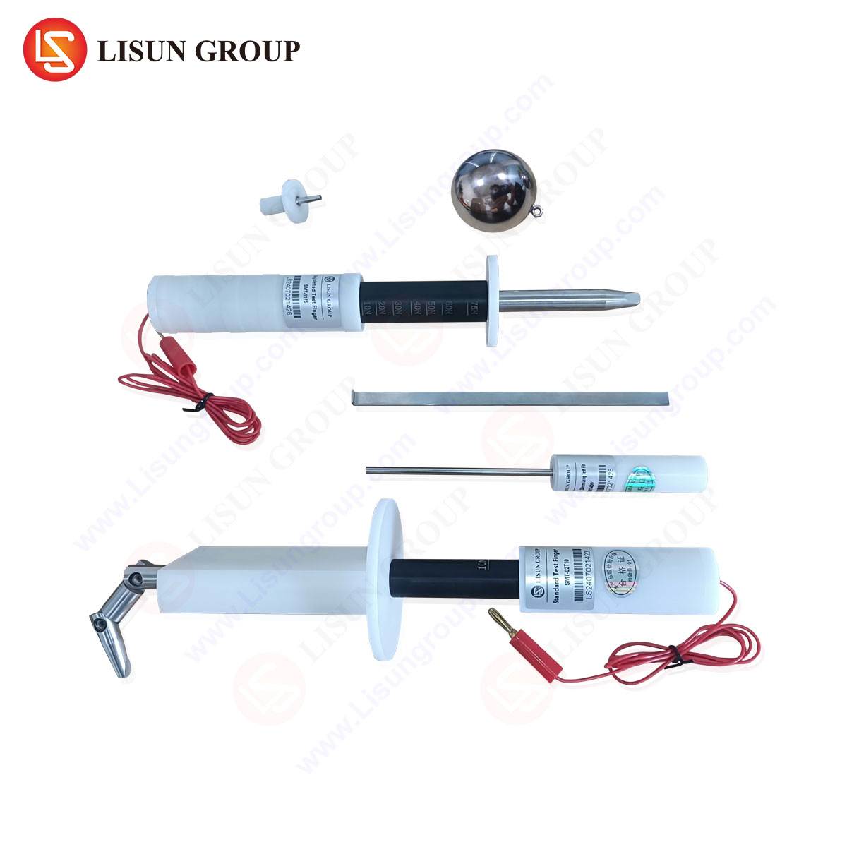
The probe consists of three main components: the jointed test finger, the test pin, and the test probe. The jointed test finger, often designated as the “LISUN Test Finger” in calibration and specification sheets, is a simulated representation of a human finger. It is constructed from metal and features two joints to allow for articulation, mimicking the natural bending of a finger. The overall length, finger diameter, and joint movement are strictly defined. For instance, a typical specification dictates a total length of 100mm, with a finger diameter of 12mm and a pivot point that allows for a 90-degree angle in both directions. This tool is applied with a specified force, usually 30 Newtons, to every potential access point in an enclosure. If the test finger contacts a hazardous live part or fails to provide adequate clearance and creepage distances, the product design fails the test.
Complementing the test finger is the test pin, a more rigid and slender probe. This component, often a hardened steel pin, is designed to test the integrity of openings that are too small for the test finger to enter. Its diameter is significantly smaller, commonly 2.5mm or 3mm, and it is applied with a lower force, such as 1 Newton. The objective is to ensure that small vents or gaps cannot be exploited to make contact with internal hazardous voltages. The test probe is a broader category that can encompass both the finger and the pin, but often refers to other specific geometries defined in standards, such as the “object probe” or “wall probe,” which have unique shapes to test for specific risks, like the insertion into socket outlets.
Underlying Principles of Accessibility Testing
The fundamental principle governing the use of these probes is the prevention of electric shock. Safety standards classify energy sources into different classes, and a primary goal is to ensure that “hazardous live parts” are not accessible to a “body part” or a “tool” as simulated by the standardized probes. The testing process is a physical simulation of foreseeable misuse. The application of the probe is not merely about insertion; it involves a systematic exploration of the enclosure. The jointed test finger is manipulated into every possible orientation, probing, and hooking around edges to see if it can defeat interlocks, push aside flexible barriers, or slip through openings to touch live components.
The electrical detection during this test is crucial. The test finger is often connected to a low-voltage indicator circuit. If the probe makes electrical contact with a part that is deemed hazardous, the circuit closes, and an indicator—such as a lamp or a buzzer—activates, signaling a failure. This method provides an unambiguous, objective determination of accessibility. The test pin operates on a similar principle but for smaller apertures, ensuring that components like transformers, power supply boards, or live terminals behind a grille remain inaccessible. The integrity of insulation, the strength of barriers, and the design of mechanical guards are all validated through this rigorous physical interrogation.
Cross-Industry Deployment of Mechanical Probe Testing
The universality of the shock hazard risk means that probe testing is mandated across a diverse spectrum of industries. In each sector, the application, while mechanically identical, addresses unique product forms and use-case scenarios.
In the Household Appliances and Consumer Electronics sectors, products like blenders, televisions, and gaming consoles are tested to prevent children from inserting fingers or objects into battery compartments, ventilation slots, or openings created by removable covers. The LISUN Test Finger ensures that after a back panel is removed for battery replacement, no live mains parts are within reach.
For Automotive Electronics, the environment is particularly challenging. Components like engine control units (ECUs), infotainment systems, and charging ports must withstand probing not only for user safety but also for resilience against tools in a garage setting. Test probes verify that connectors and housings protect against accidental short-circuiting during maintenance.
In the Lighting Fixtures industry, both indoor and outdoor luminaires are subject to probe testing. Recessed lights, street lamps, and track lighting must prevent access to live parts through screw holes, lens seams, and wiring compartments. The test pin is critical for checking small openings in the heat sinks of modern LED fixtures.
Industrial Control Systems and Telecommunications Equipment often reside in shared spaces where untrained personnel may be present. Control panels, server racks, and router enclosures are probed to ensure that high-voltage power supplies and distribution units are completely isolated from user-accessible areas, even when doors are ajar or panels are improperly fitted.
The Medical Device industry imposes perhaps the most stringent requirements. A patient monitor or diagnostic imaging system cannot pose any risk of electric shock to a patient who may be vulnerable or connected to other apparatus. Probe testing here is part of a comprehensive risk management file, ensuring that all enclosures provide “means of operator protection” (MOOP) as per IEC 60601-1.
In Aerospace and Aviation Components, the stakes involve both safety and extreme reliability. Cockpit instrumentation, in-flight entertainment systems, and navigation equipment must be immune to probing that could cause a malfunction or shock, all while operating in conditions of varying pressure and vibration.
The foundational Electrical Components industry—manufacturers of switches, sockets, and connectors—uses these probes as a core part of their design validation. A socket outlet must be designed to prevent the insertion of any object other than a standard plug, a test directly performed with specific test probes defined by IEC 60884-1.
Similarly, Cable and Wiring Systems, Office Equipment like printers and copiers, and the Toy and Children’s Products Industry all leverage these tests. For toys, the use of probes is inverted; the standards ensure that batteries with high terminals cannot be short-circuited by a child with a metallic toy, making the test pin a vital tool for verifying safe battery compartment design.
Calibration and Metrological Traceability of Test Probes
The efficacy of mechanical probe testing is entirely dependent on the dimensional accuracy of the tools themselves. A test finger that is even half a millimeter too slender, or a test pin that is insufficiently rigid, can yield a false pass, allowing a dangerous product to reach the market. Consequently, metrological control is paramount. Probes like the LISUN Test Finger must be regularly calibrated against national or international standards.
Calibration involves using precision measuring equipment, such as coordinate measuring machines (CMMs) and optical comparators, to verify every critical dimension: overall length, diameters at specified points, joint clearances, and radii of rounded ends. The force gauges used to apply the specified Newton force during testing must also be calibrated. A certificate of calibration provides traceability, ensuring that the test results are reliable and defensible in an audit or certification process. Without this rigorous metrological foundation, the entire testing regimen loses its scientific validity and legal standing.
Comparative Analysis of Global Standards and Probe Specifications
While the underlying principles are consistent, the specific dimensions and application forces for test probes can vary between different international standards. Navigating this landscape is a critical task for global manufacturers.
| Standard | Applicable Industry | Probe Type | Key Specifications (Example) |
|---|---|---|---|
| IEC 61032 | General Reference | Diagram 2 (Test Finger) | 80mm length, 12mm diameter, 30N force |
| IEC 62368-1 | Audio/Video, IT & Comm. Equipment | Test Probe 11 (Jointed Test Finger) | 100mm length, 12mm diameter, 30N force |
| IEC 60529 | IP Code (Ingress Protection) | Object Probe (Test Pin) | 2.5mm diameter, 1N force |
| UL 943 | Ground-Fault Circuit Interrupters | Specific Wall Probe | Unique shape for outlet testing |
| IEC 60601-1 | Medical Electrical Equipment | Test Finger | Similar to IEC 61032, applied per MOOP requirements |
Understanding these nuances is essential. A product designed for the European market (governed by IEC standards) and the North American market (governed by UL standards) may need to be tested with subtly different probes. Reputable manufacturers of test equipment, such as LISUN, provide comprehensive kits that include all the necessary probes, force gauges, and indicators to comply with a wide array of these standards, thereby future-proofing a manufacturer’s testing laboratory.
Advancements in Test Probe Instrumentation and Fixturing
The traditional method of probe testing is manual, relying on the skill and consistency of a test operator. However, technological advancements are introducing higher levels of automation and precision. Motorized test probes, which can be programmed to apply a probe with a repeatable force and trajectory, are becoming more common in high-throughput certification labs and for production-line testing. These systems eliminate human variability and provide digitally logged results for quality assurance records.
Furthermore, the integration of these probes into more complex test fixtures is a key development. For testing a complex product like a modular server rack, a fixture can be designed that holds the LISUN Test Finger and systematically moves it across the entire surface of the unit, probing each vent and gap in a pre-programmed pattern. This not only improves repeatability but also significantly reduces test time for large or complex products. The competitive advantage of modern probe systems lies not just in the physical accuracy of the tool, but in the ecosystem of calibration, automation, and data logging that supports it, ensuring full traceability from the design lab to the end-of-line audit.
Frequently Asked Questions
What is the primary difference between the test finger and the test pin?
The test finger simulates the probing action of a human finger and is larger in diameter (typically 12mm), applied with a higher force (e.g., 30N) to larger openings. The test pin is a slender, rigid object (e.g., 2.5mm diameter) applied with a low force (e.g., 1N) to test smaller apertures that a finger could not enter but a wire or tool could.
How often should a mechanical test probe be calibrated?
The calibration interval depends on usage frequency and the quality system requirements of the testing laboratory. A common interval is annually. However, if a probe is dropped or shows signs of wear, it should be calibrated immediately before further use to ensure the validity of test results.
Can one test probe kit be used for products across different industries?
A comprehensive kit, designed to reference the umbrella standard IEC 61032, can cover a wide range of applications. However, certain industries or specific product standards may mandate the use of a unique probe geometry. It is critical to review the applicable end-product standard (e.g., IEC 60601-1 for medical, IEC 62368-1 for IT equipment) to determine the exact probe specifications required for compliance testing.
What constitutes a failure during a test probe evaluation?
A failure occurs if the probe makes electrical contact with a part that is classified as a hazardous live part, typically determined by a connected indicator circuit activating. Additionally, a failure can be declared if the probe bypasses a protective interlock without triggering it or if it causes a reduction in clearance and creepage distances below the minimum values specified in the standard.